Blind Spot Radar
Components and Component Location
Component Location
[4DR]
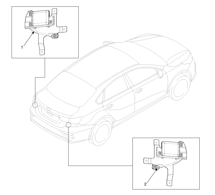
| 1. BSD Radar (Master) | 2. BSD Radar (Slave) |
[5DR]
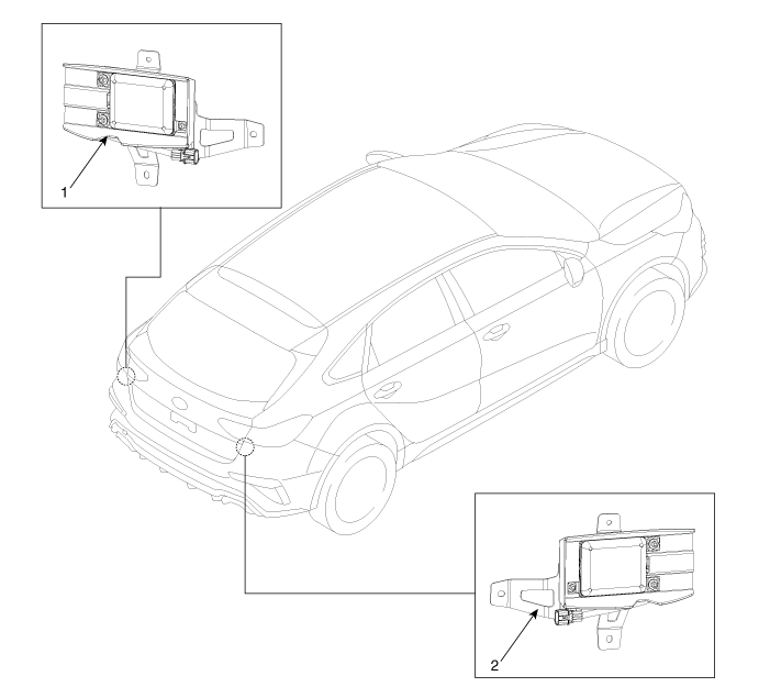
| 1. BSD Radar (Master) | 2. BSD Radar (Slave) |
Circuit Diagrams
Wiring Diagram
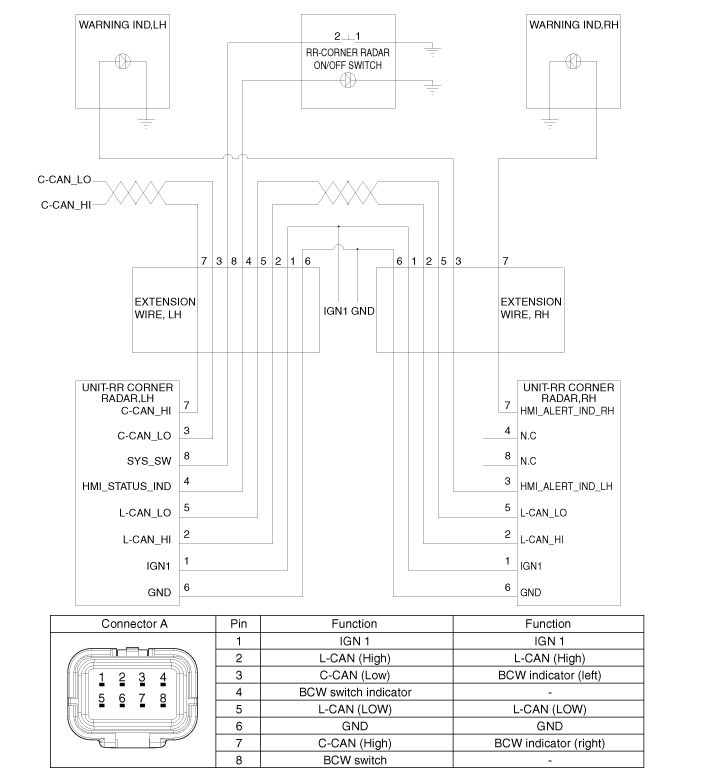
Repair Procedures
Removal
Disconnect the negative (-) battery terminal.
Remove the rear bumper assembly.
(Refer to Body - "Rear Bumper Assembly")
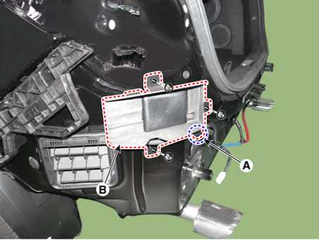
Disconnect the connector (A) and remove the BSD radar unit (B) by loosening the nuts.
Tightening torque: 8.8–10.8 N·m
[4DR]
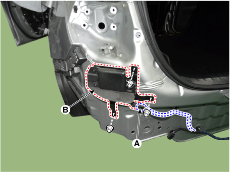
[5DR]
Installation
Install in the reverse order of removal.
Adjustment
Blind Spot Radar Angle Adjustment
Remove the rear bumper assembly.
(Refer to Body - "Rear Bumper Assembly")
Establish the vehicle centerline using the blind spot radar adjustment tool kit (09958-3T000 or 09958-3T500).
[9958-3T000]
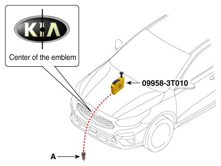
Attach the vertical plumb bob (09958-3T010) to the hood and lower the plumb bob (A) to the ground so that it passes through the center of the emblem.
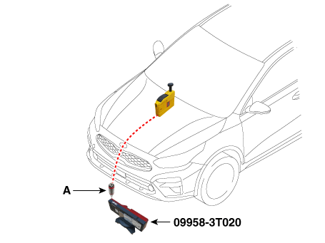
Install the optical receiver (09958-3T020) under the plumb bob (A).
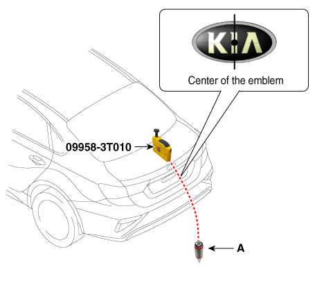
Attach the vertical plumb bob (09958-3T010) to the luggage compartment and lower the plumb bob (A) to the ground so that it passes through the center of the emblem.
[4DR]
[5DR]
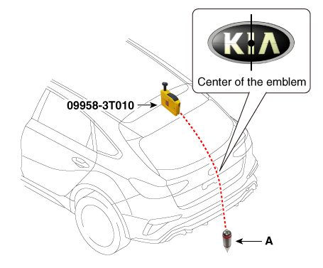
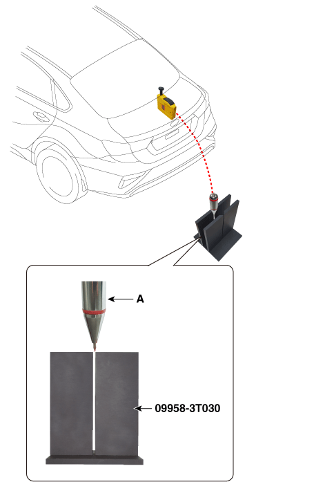
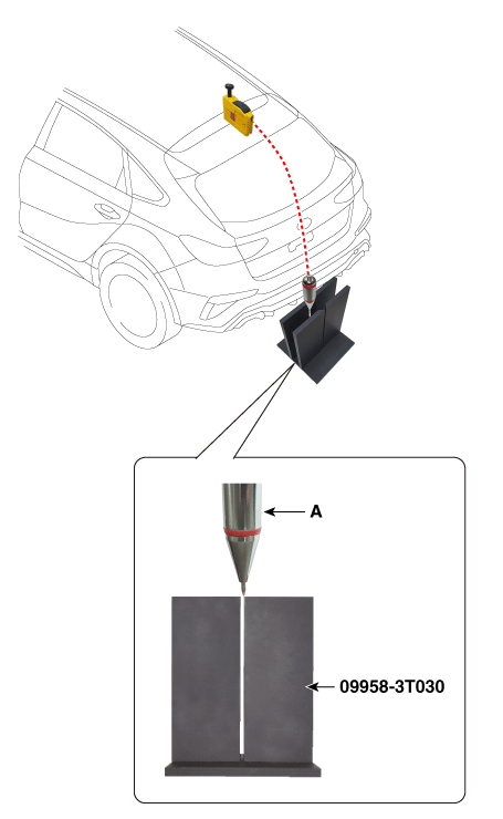
Install the rear alignment template (09958-3T030) so that its hole is located directly under the plumb bob (A).
[4DR]
[5DR]
Place the laser support (09958-3T040) at a distance of "2 m" behind the vehicle and install the laser level (09958-3T060) on the laser support.
[4DR]
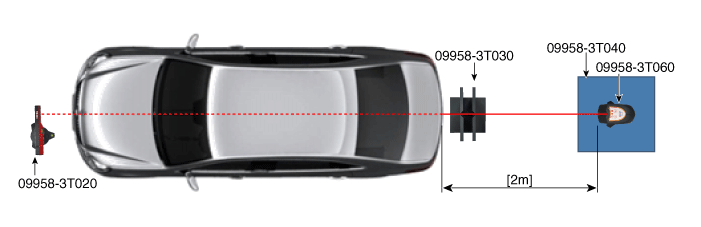
[5DR]
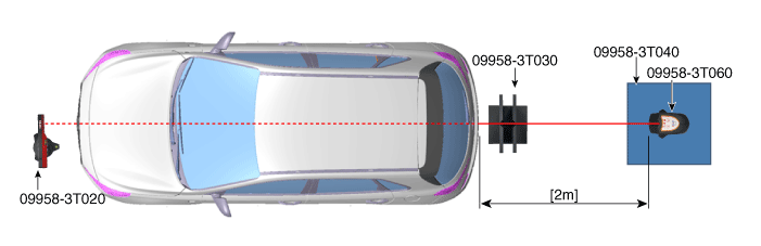
[9958-3T500]
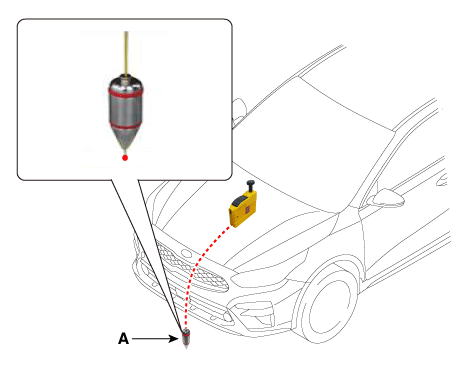
Attach the vertical plumb bob (09958-3T010) to the hood and lower the plumb bob (A) to the ground so that it passes through the center of the emblem.
Mark the center point under the plumb bob (A).
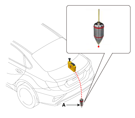
Attach the vertical plumb bob (09958-3T010) to the luggage compartment and lower the plumb bob (A) to the ground so that it passes through the center of the emblem.
[4DR]
[5DR]
Mark the center point under the plumb bob (A).
[4DR]
[5DR]
Pass a string under the vehicle from the rear to the front and secure the string at the center point (A) of the front of the vehicle.
Secure the string at point (C), approximately 1.5–2 m from the rear of the vehicle, so that it passes through the rear center point (B).
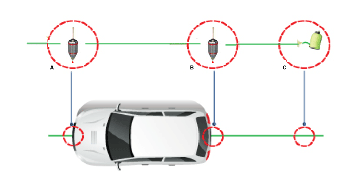
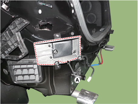
Tighten the nuts after removing the BCW radar absorber (A) by loosening the mounting nuts. (5DR only)
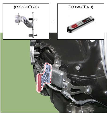
Install the fixing adapter (09958-3T080) on the radar unit and secure the laser level (09958-3T070).
[4DR]
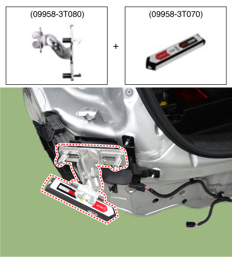
[5DR]
Measure the horizontal angle.
Specified angle: 4DR: 54° / 5DR: 52°
[9958-3T000]
Install the angle measuring plate (09958-3T050) at the point where the center laser beam (A) and the horizontal laser beam (B) intersect.
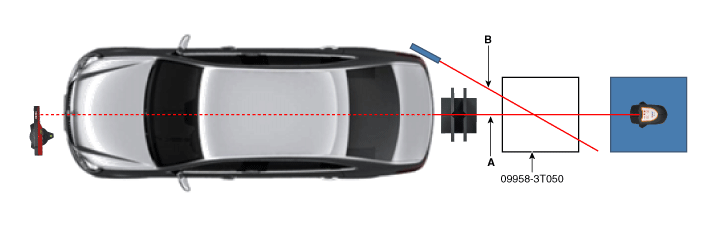
Measure the angle (C) between the centerline (A) of the angle measuring plate and the horizontal laser beam (B) using the digital protractor (09958-3T090).
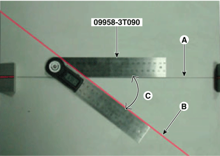
[9958-3T500]
Measure the angle (C) between the centerline (A) of the angle measuring plate and the horizontal laser beam (B) using the digital protractor (09958-3T090).
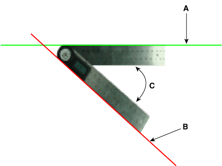
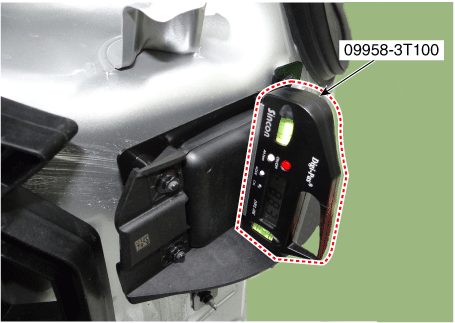
Measure the vertical angle of the blind spot radar using the digital inclinometer (09958-3T100).
Specified angle: 90°
Install the BCW radar absorber on the BCW unit. (5DR only)
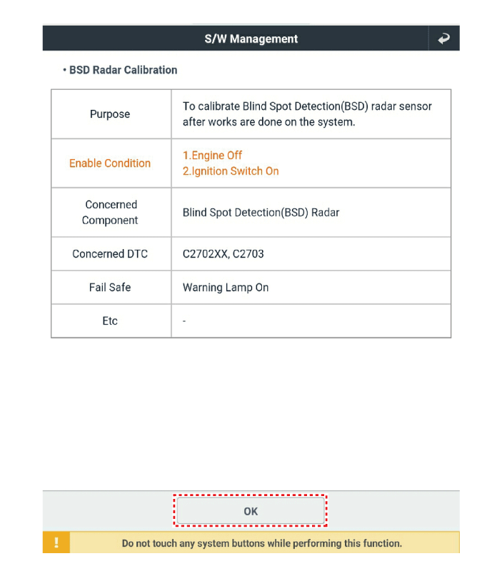
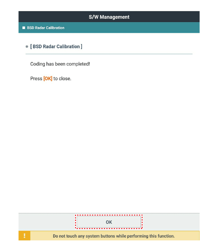
After checking and correcting the angle of the blind spot radar unit, perform the BCW radar calibration procedure using KDS.
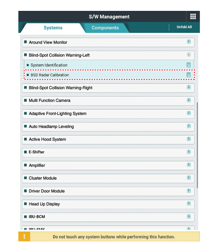
Test yourself
A quick Kia Forte BD quiz: every answer comes with an explanation and a link to the manual page.