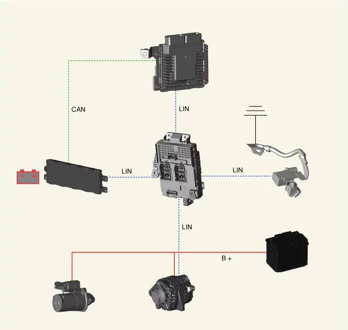
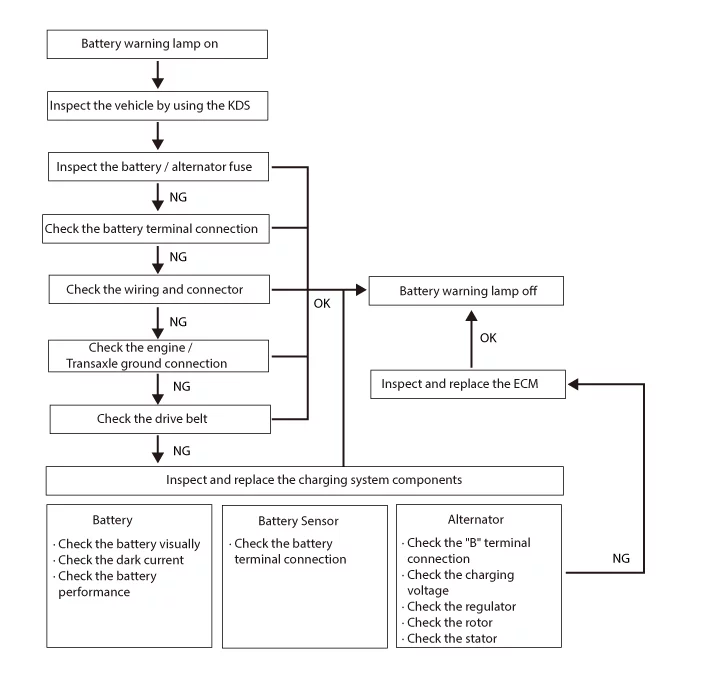
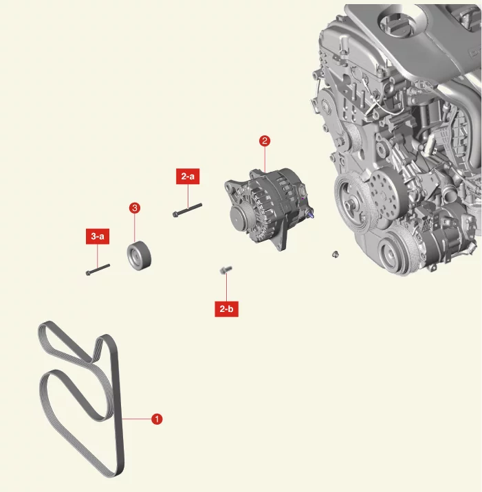
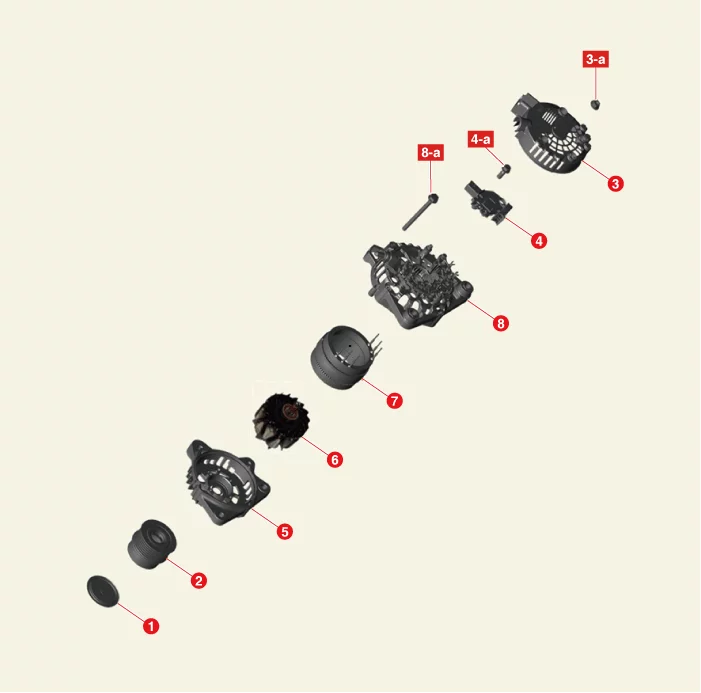
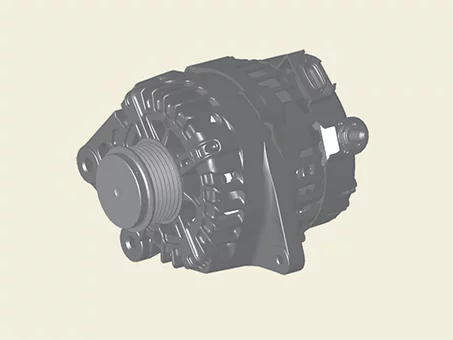
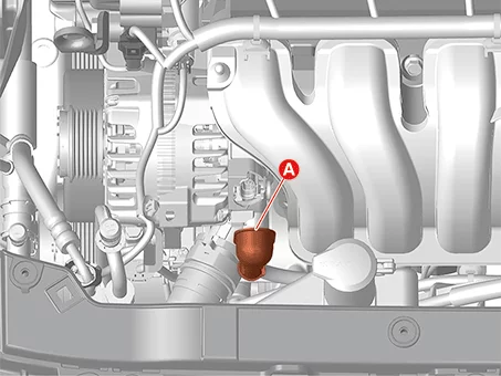
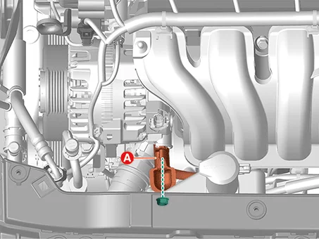
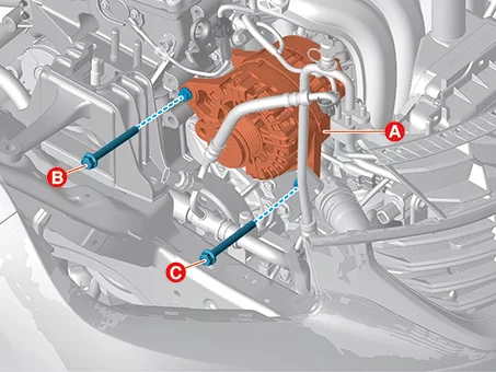
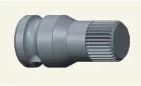
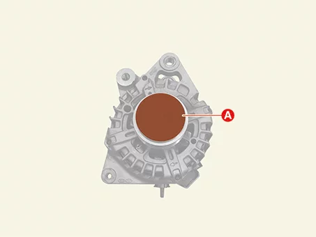
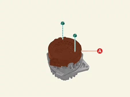
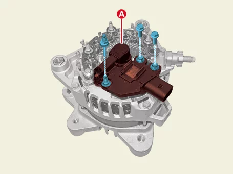
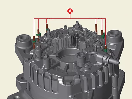
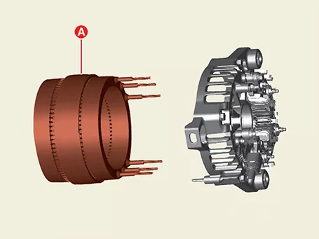
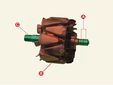
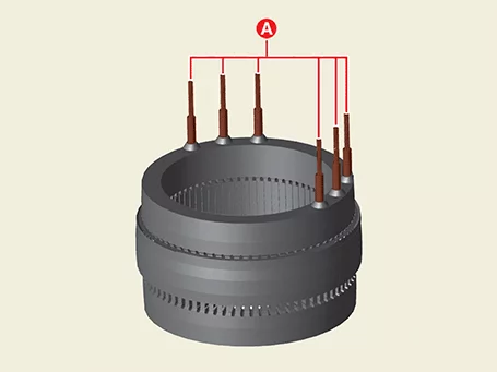
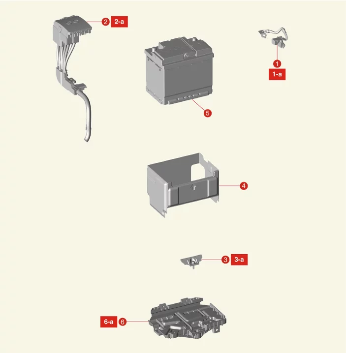
The alternator consists of a rotor, stator, rectifier, brush, regulator, bearing, and a pulley.
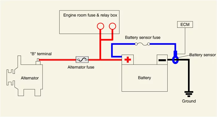
A diode integrated in alternator acts as a rectifier. Rectifier circuit containing diodes converts alternating current (AC) into direct current (DC) and supply it to the alternator B terminal.
Engine Control Module (ECM) controls the amount of electricity generated by charging control, discharging control and normal control according to the battery status and the electricity usage of the vehicle.
Alternator Management System (AMS)
Alternator Management System (AMS) improves fuel efficiency and manages the battery charging state by checking vehicle driving conditions, electric load, and battery state.
The Engine Control Module (ECM) controls generating voltage by duty cycle (charging control, discharging control, normal control) based on the battery conditions and vehicle operating conditions.
The ECM performs discharging control during acceleration to consume battery power and lighten the load on the alternator. The ECM performs charging control during deceleration to charge the battery.
The alternator consists of a rotor, stator, rectifier, brush, regulator, bearing, and pulley.
A diode integrated in alternator acts as a rectifier. Rectifier circuit containing diodes converts alternating current (AC) into direct current (DC) and supply it to the alternator B terminal.
The Engine Control Module (ECM) controls generating voltage by duty cycle (charging control, discharging control, normal control) based on the battery conditions and vehicle operating conditions.
The Absorbent Glass Material (AGM) battery controls the electrolyte by absorbing the electrolyte into the absorbent glass fiber separator inside the battery, and the valve installed on the top of the battery minimizes gas release.
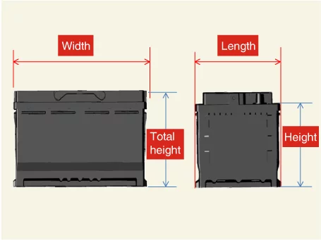
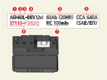
Battery Label Information
Battery specifications
AGM : Absorbent Glass Material
CMF : Closed Maintenance Free
MF : Maintenance Free
Battery capacity (20 Ah)
Terminal location
L : battery positive ( + ) terminal on the left.
R : battery positive ( + ) terminal on the right.
Battery type
BCI (Battery Council International) : Intruding terminal
DIN (Deutsche Industric Normen) : Recessed terminal
Cold Cranking Ampere (CCA)
CCA : The amount of current that can be supplied for 30 seconds while maintaining a voltage of more than 7.2 V at -18°C (-0.4°F).
Part number
Reserve Capacity (RC)
RC : The amount of time that can be supplied 25 A while maintaining the minimum voltage of 10.5 V at 27 °C.
Carefully inspect the battery case for cracks or leakage of electrolytes, and wear thick rubber gloves to prevent the electrolyte from contacting the skin when disconnecting the battery.
Battery
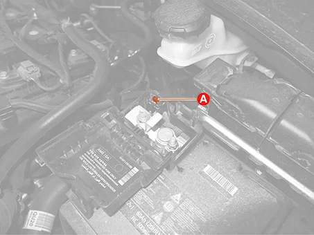
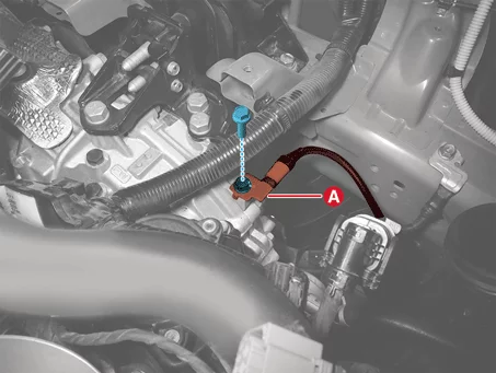
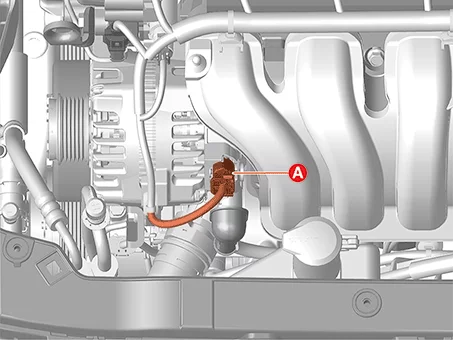
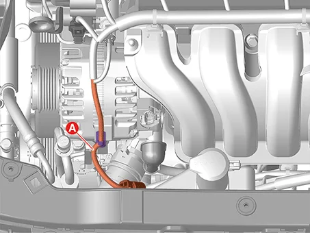
Disconnect the battery negative ( - ) terminal (A).
Tightening torque : 7.8 - 9,8 N·m
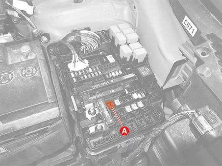
Open the cover and disconnect the battery positive ( + ) terminal after removing the nut.
Tightening torque : 7.8 - 9,8 N·m
Remove the clamp (A) after removing the bolt.
Tightening torque : 8.8 - 13,7 N·m
Remove the battery (A).
Battery Tray
Remove the air cleaner assembly. (Refer to Engine Mechanical System - "Air Cleaner")
Remove the Engine Control Module (ECM). (Refer to Engine Control / Fuel System - "Engine Control Module (ECM)")
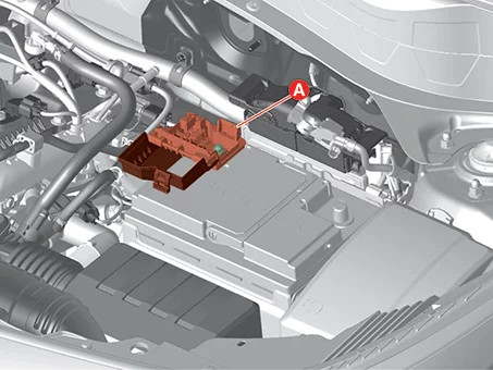
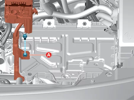
Remove the wiring protector (A) after removing the bolt.
Tightening torque : 9.8 - 11,8 N·m
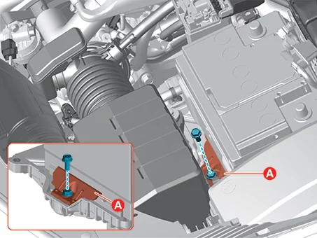
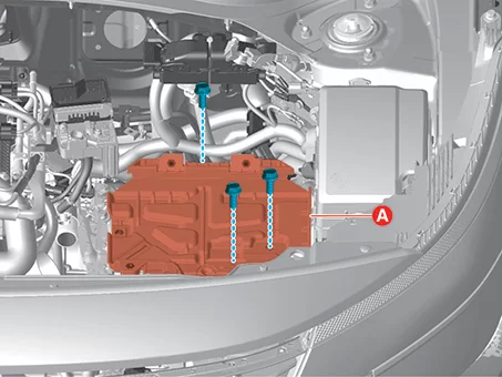
Remove the battery tray (A) after removing bolts.
Tightening torque : 8.8 - 13,7 N·m
Installation
Install in reverse order of removal.
Install the battery and battery tray to the specified torque.
If the battery is dropped, it may cause internal damage. (Do not reuse)
When installing the battery, fix the clamp on the tray correctly.
When installing the battery ( - ) terminal, be sure to observe the specified torque before tightening. When tightening with excessive torque, the circuit inside the PCB of the battery sensor and the battery terminals may be damaged.
When replacing the battery, be sure to replace it with the same specification(capacity, manufacturer, etc.) as the battery installed originally. When the different specification is installed, it may be determined that the battery performance is abnormal by the battery sensor.
Battery Cleaning
Cleaning
Remove the battery. (Refer to Battery - "Removal and Installation")
If the battery tray area is damaged due to an electrolyte leak, dissolve baking soda in warm water to clean the damaged area. Rub the damaged area with a stiff brush or the like, then wipe with a cloth moistened with an aqueous solution of baking soda.
Wash the upper part of the battery with an aqueous solution of baking soda.
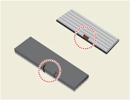
Check the battery case and cover for the cracks, and replace the battery if any cracks are found.
Clean the battery post with a suitable tool.
Clean the inside of the battery terminal clamp with a suitable tool and replace any damaged cables or damaged terminal clamps.
Install the battery in the reverse order of removal.
Battery Sensor Specification
Specification
Item
Specification
Rated voltage (V)
12 - 14
Operating voltage (V)
6 - 18
Operating temperature [°C (°F)]
-40 to 105 (-40 to 221)
Parasitic Current (uA)
Maximum 300
Battery Sensor Description and Operation
Description
Battery sensor is mounted on the battery negative ( - ) terminal. It transmits battery voltage, current, temperature information to Engine Control Module (ECM). ECM controls generating voltage by duty cycle based on these signals.
Battery Sensor On Vehicle Inspection
On Vehicle Inspection
Inspect the parasitic current. (Refer to Charging System - "Battery")
If the parasitic current is more than 100 mA, a fault code may occur in the battery sensor. If the battery sensor fault code is displayed, measure the parasitic current first before proceeding with the battery sensor replacement procedure.
If the parasitic current is normal, replace the battery sensor and perform the following procedure.
Turn the IG ON/OFF once and park the vehicle for at least 4 hours at room temperature. In order to measure the initial value of the State of Charge (SOH) of the battery, battery needs stabilization time.
After 4 hours, START ON/OFF twice or more and check the State of Function (SOF) of the battery by using the KDS.
Battery Sensor Removal and Installation
Removal
Remove the Engine Control Module (ECM). (Refer to Engine Control / Fuel System - "Engine Control Module (ECM)")
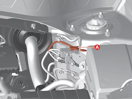
Disconnect the battery sensor connector (A).
Remove the battery sensor (A) after removing the bolt.
Tightening torque : 26.5 - 32 N·m
Installation
Install in reverse order of removal.
Install the battery sensor to the specified torque.
If the battery sensor is dropped, it may cause internal damage. (Do not reuse)
When installing the battery ( - ) terminal, be sure to observe the specified torque before tightening. When tightening with excessive torque, the circuit inside the PCB of the battery sensor and the battery terminals may be damaged.
When replacing the battery, be sure to replace it with the same specification(capacity, manufacturer, etc.) as the battery installed originally. When the different specification is installed, it may be determined that the battery performance is abnormal by the battery sensor.