Suspension System

Components and Components Location

80steps
~480min
4/5difficulty
060120180240300176.5130N·mlb·ft
Tightening torque found on this page
Done 0 of 80

Contents:

Components and Components Location

Component

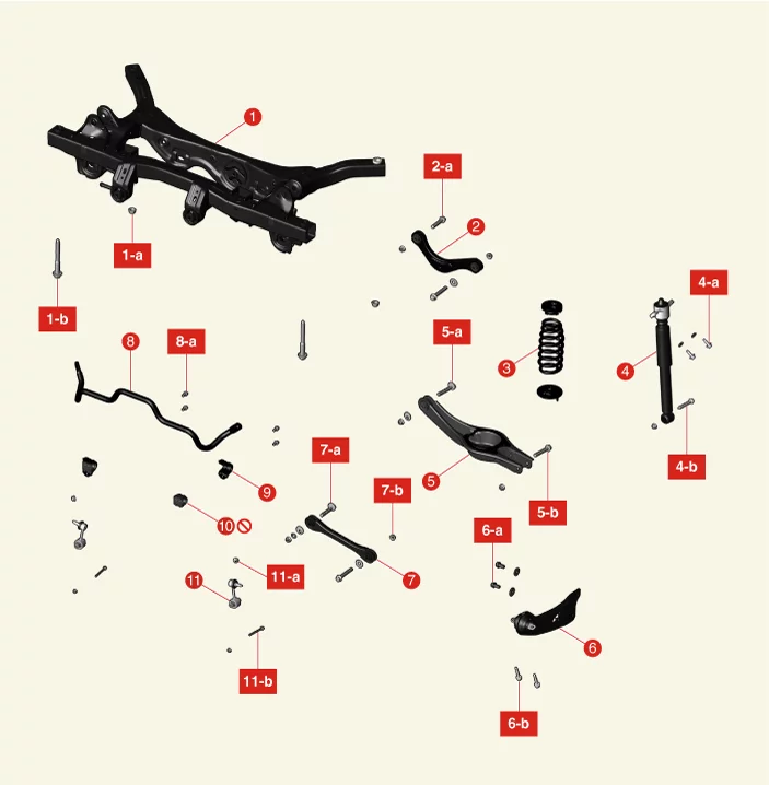
Suspension System — Rear Suspension System - Multi Link / Components and Components Location / Component illustration
1. Rear Cross Member
1-a. 156.9 - 176 N·m
1-b. 156.9 - 176 N·m
2. Rear Upper Arm
2-a. 137.3 - 157 N·m
3. Coil Spring
4. Rear Shock Absorber
4-a. 58.8 - 74 N·m
4-b. 98.1 - 118 N·m
5. Rear Lower Arm
5-a. 107.9 - 118 N·m
5-b. 137.3 - 157 N·m
6. Trailing Arm
6-a. 137.3 - 157 N·m
6-b. 98.1 - 118 N·m
7. Rear Assist Arm
7-a. 107.9 - 118 N·m
7-b. 137.3 - 157 N·m
8. Rear Stabilizer Bar
8-a. 44.1 - 54 N·m
9. Rear Stabilizer Bar Bracket
10. Rear Stabilizer Bar Bushing
11. Rear Stabilizer Bar Link
11-a. 58.8 - 78 N·m
11-b. 19.6 - 29 N·m

Rear Shock Absorber Components and Components Location

Component and Component Location

Suspension System — Rear Suspension System - Multi Link / Rear Shock Absorber / Components and Components Location / Component and Component Location illustration
1. Insulator Cap
2. Retainer
3. Insulator
3-a. 49.0 - 64 N·m
4. Retainer Cup
5. Bumper Rubber
6. Dust Cover
7. Shock Absorber Assembly
7-a. 21.6 - 29 N·m
7-b. 98.1 - 118 N·m

Rear Shock Absorber Removal and Installation

Removal

  1. Remove the rear wheel and tires. (Refer to Tires/Wheels - "Wheel")
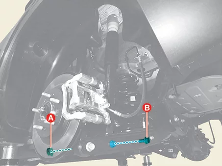
  2. Remove the rear shock absorber lower nut (A) and bolt (B).

    Tightening torque : 98.1 - 118 N·m

    Suspension System — Rear Suspension System - Multi Link / Rear Shock Absorber / Removal and Installation / Removal illustration
    Warning
    Be careful not to apply excessive load when using a 2-post lift. The vehicle may fall.
    Note
    • Install the transmission jack and lift up the parts to prevent the bolts and nuts from damage when installing or removing.
    • Be careful not to change the bolt, nut and washer installing position.
    Information
    Fix the bolt and remove or install the nut.
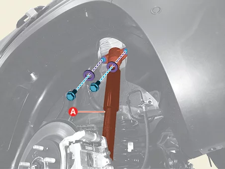
  3. Remove the rear shock absorber (A) after removing the bolts and washers.

    Tightening torque : 58.8 - 74 N·m

    Suspension System — Rear Suspension System - Multi Link / Rear Shock Absorber / Removal and Installation / Removal illustration

Installation

  1. Install in reverse order of removal.

Rear Shock Absorber Disassembly

Special Service Tool

Tool Name / Number Illustration Description
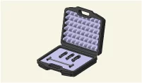
Shock absorber lock nut remover.
09546 - 3X100
Suspension System — Rear Suspension System - Multi Link / Rear Shock Absorber / Disassembly / Special Service Tool illustration
Used for removal or installing of rear shock absorber lock nut.

Disassembly

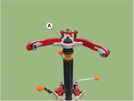
  1. Remove the insulator cap (A).
    Suspension System — Rear Suspension System - Multi Link / Rear Shock Absorber / Disassembly illustration
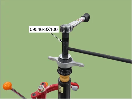
  2. Remove the self locking nut using the SST (09546 - 3X100).

    Tightening torque : 21.6 - 29 N·m

    Suspension System — Rear Suspension System - Multi Link / Rear Shock Absorber / Disassembly illustration
    Note
    Do not reuse the lock nut.
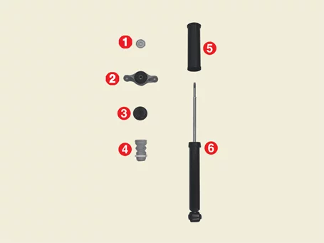
  3. Disassemble the rear shock absorber.
    Suspension System — Rear Suspension System - Multi Link / Rear Shock Absorber / Disassembly illustration
    Information
    Disassemble the rear shock absorber assembly by the following orders below. 1 → 2 → 3 → 4 → 5 → 6
    Number Item Number Item
    1 Retainer 4 Bumper rubber
    2 Insulator assembly 5 Dust cover
    3 Cup 6 Shock absorber assembly

Rear Shock Absorber Inspection

Inspection

  1. Check the rubber parts for damage or deterioration.
  2. Check all bolts and nuts.
  3. Repeat compression and tension of the rear shock absorber rod (A) to check for abnormal resistance or noise between operations.
    Suspension System — Rear Suspension System - Multi Link / Rear Shock Absorber / Inspection illustration

Disposal

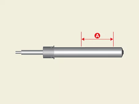
  1. Fully extend the piston rod.
  2. Drill a hole on the A section to remove gas from the cylinder.
    Suspension System — Rear Suspension System - Multi Link / Rear Shock Absorber / Inspection / Disposal illustration
    Information
    The gas coming out is harmless, but be careful of debris that may fly when drilling.

Rear Shock Absorber Reassembly

Special Service Tool

Tool Name / Number Illustration Description
Shock absorber lock nut remover.
09546 - 3X100
Suspension System — Rear Suspension System - Multi Link / Rear Shock Absorber / Reassembly / Special Service Tool illustration
Used for removal or installing of rear shock absorber lock nut.

Reassembly

  1. Reassemble the rear shock absorber assembly.
    Suspension System — Rear Suspension System - Multi Link / Rear Shock Absorber / Reassembly illustration
    Information
    Reassemble the rear shock absorber assembly by the following orders below. 6 → 5 → 4 → 3 → 2 → 1
    Number Item Number Item
    1 Retainer 4 Bumper rubber
    2 Insulator assembly 5 Dust cover
    3 Cup 6 Shock absorber assembly
  2. Install the self locking nut using the SST (09546 - 3X100).

    Tightening torque : 21.6 - 29 N·m

    Suspension System — Rear Suspension System - Multi Link / Rear Shock Absorber / Reassembly illustration
    Note
    Do not reuse the self locking nut.
  3. Remove the insulator cap (A).
    Suspension System — Rear Suspension System - Multi Link / Rear Shock Absorber / Reassembly illustration

Rear Coil Spring Components and Components Location

Component and Component Location

Suspension System — Rear Suspension System - Multi Link / Rear Coil Spring / Components and Components Location / Component and Component Location illustration
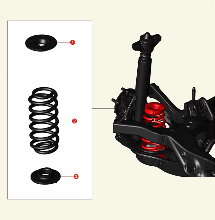
1. Coil Spring Upper Pad
2. Coil Spring
3. Coil Spring Lower Pad

Rear Coil Spring Removal and Installation

Removal

Warning
If a transmission jack is used with a two-post lift, do not lift the vehicle too much. The center gravity of the vehicle may change and fall.
  1. Remove the rear wheel and tires. (Refer to Tires/Wheels - "Wheel")
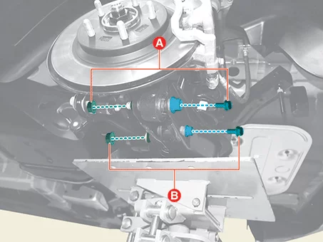
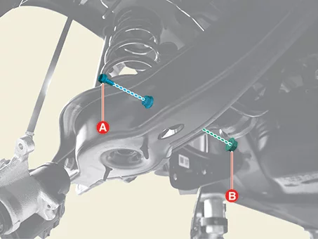
  2. Remove the rear lower arm bolts and nuts (A, B).
    Tightening torque : (A) : 137.3 - 157 N·m (B) : 98.1 - 118 N·m
    Suspension System — Rear Suspension System - Multi Link / Rear Coil Spring / Removal and Installation / Removal illustration
    Note
    • Install the transmission jack and lift up the parts to prevent the bolts and nuts from damage when installing or removing.
    • Be careful not to change the bolt, nut and washer installing position.
    Information
    Fix the bolt and remove or install the nut.
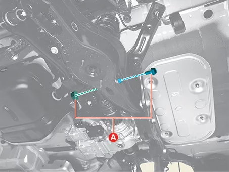
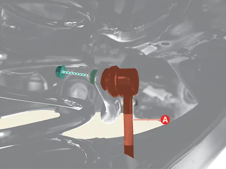
  3. Remove the rear stabilizer bar link nut and bolt (A).

    Tightening torque : 19.6 - 29 N·m

    Suspension System — Rear Suspension System - Multi Link / Rear Coil Spring / Removal and Installation / Removal illustration
    Note
    • Install the transmission jack and lift up the parts to prevent the bolts and nuts from damage when installing or removing.
    • Be careful not to change the bolt, nut and washer installing position.
    Information
    Fix the bolt and remove or install the nut.
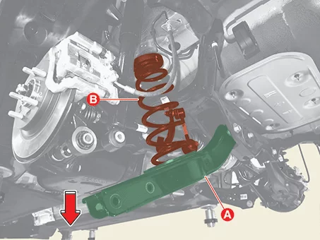
  4. Down the rear lower arm (A), and then remove the rear coil spring (B).
    Suspension System — Rear Suspension System - Multi Link / Rear Coil Spring / Removal and Installation / Removal illustration
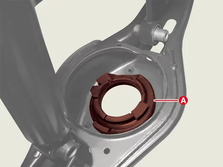
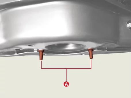
  5. Remove the rear coil spring lower pad (A) from the rear lower arm.
    Suspension System — Rear Suspension System - Multi Link / Rear Coil Spring / Removal and Installation / Removal illustration

Installation

  1. Install in reverse order of removal.
    Note
    • Check the rear coil spring lower pad protrusion (A) bottom of the rear lower arm after installation, if the protrusion (A) is not exposed completely, reinstall the rear coil spring lower pad.
      Suspension System — Rear Suspension System - Multi Link / Rear Coil Spring / Removal and Installation / Installation illustration
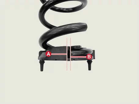
    • When installing the rear coil spring, mount it so that the surface (A) of the lower pad of the spring and the end of the spring (B) contact as much as possible.

      Maximum allowable gap : 3 mm (0.11 in.)

      Suspension System — Rear Suspension System - Multi Link / Rear Coil Spring / Removal and Installation / Installation illustration
  2. Check the alignment. (Refer to Alignment - "Repair Procedures")

Rear Coil Spring Inspection

Inspection

  1. Check the coil spring for cracks or deformation.
  2. Check the coil spring pad for damage and deformation.
Rear Upper Arm Components and Components Location

Component and Component Location

Suspension System — Rear Suspension System - Multi Link / Rear Upper Arm / Components and Components Location / Component and Component Location illustration
1. Rear Upper Arm
1-a. 137.3 - 157 N·m
1-b. 137.3 - 157 N·m

Rear Upper Arm Removal and Installation

Removal

Warning
If a transmission jack is used with a two-post lift, do not lift the vehicle too much. The center gravity of the vehicle may change and fall.
  1. Remove the rear wheel and tires. (Refer to Tires/Wheels - "Wheel")
  2. Remove the rear upper arm bolt (A), washer (B), and nut (C).

    Tightening torque : 137.3 - 157 N·m

    Suspension System — Rear Suspension System - Multi Link / Rear Upper Arm / Removal and Installation / Removal illustration
    Note
    • Install the transmission jack and lift up the parts to prevent the bolts and nuts from damage when installing or removing.
    • Be careful not to change the bolt, nut and washer installing position.
    Information
    Fix the bolt and remove or install the nut.
  3. Remove the rear upper arm (A) after removing the bolt.

    Tightening torque : 137.3 - 157 N·m

    Suspension System — Rear Suspension System - Multi Link / Rear Upper Arm / Removal and Installation / Removal illustration
    Note
    Install the transmission jack and lift up the parts to prevent the bolts and nuts from damage when installing or removing.

Installation

  1. Install in reverse order of removal.
  2. Check the alignment. (Refer to Alignment - "Repair Procedures")

Rear Upper Arm Inspection

Inspection

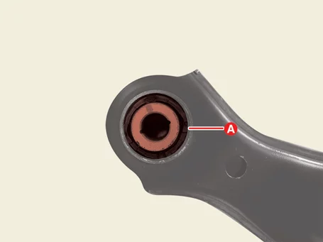
  1. Check the bushing (A) for wear and aging.
    Suspension System — Rear Suspension System - Multi Link / Rear Upper Arm / Inspection illustration
  2. Check the rear upper arm for bent or damage.
  3. Check all bolts and nuts.

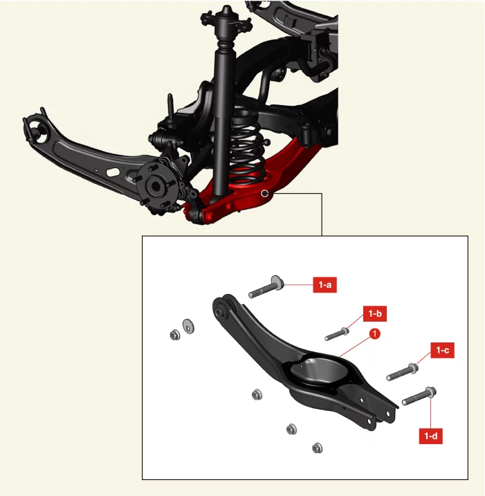
Rear Lower Arm Components and Components Location

Component and Component Location

Suspension System — Rear Suspension System - Multi Link / Rear Lower Arm / Components and Components Location / Component and Component Location illustration
1. Rear Lower Arm
1-a. 107.9 - 118 N·m
1-b. 19.6 - 29 N·m
1-c. 98.1 - 118 N·m
1-d. 137.3 - 157 N·m

Rear Lower Arm Removal and Installation

Removal

  1. Remove the rear coil spring. (Refer to Rear Suspension System - "Rear Coil Spring")
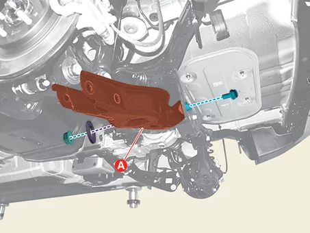
  2. Remove the rear lower arm (A) after removing the bolt, nut, and plate.

    Tightening torque : 107.9 - 118 N·m

    Suspension System — Rear Suspension System - Multi Link / Rear Lower Arm / Removal and Installation / Removal illustration
    Note
    • Install the transmission jack and lift up the parts to prevent the bolts and nuts from damage when installing or removing.
    • Be careful not to change the bolt, nut and washer installing position.
    Information
    Fix the bolt and remove or install the nut.

Installation

  1. Install in reverse order of removal.
    Note
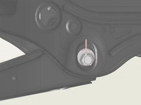
    When tightening the nut, align the center of the bolt plate scale with the center of the guide.
    Suspension System — Rear Suspension System - Multi Link / Rear Lower Arm / Removal and Installation / Installation illustration
  2. Check the alignment. (Refer to Alignment - "Repair Procedures")

Rear Lower Arm Inspection

Inspection

  1. Check the bushing for wear and aging.
  2. Check the rear lower arm for bent or damage.
  3. Check all bolts and nuts.

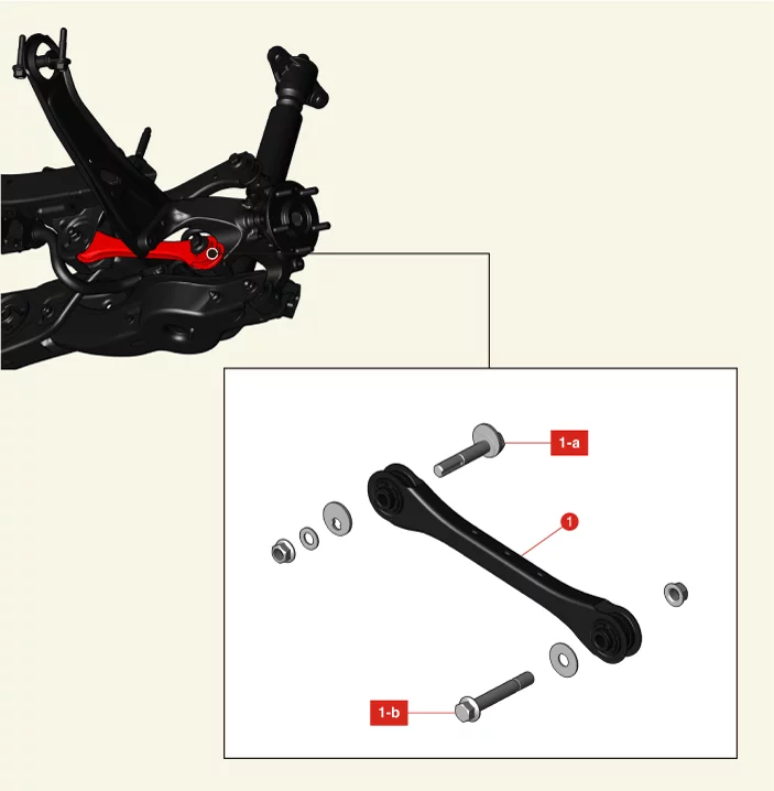
Rear Assist Arm Components and Components Location

Component and Component Location

Suspension System — Rear Suspension System - Multi Link / Rear Assist Arm / Components and Components Location / Component and Component Location illustration
1. Rear Assist Arm
1-a. 107.9 - 118 N·m
1-b. 137.3 - 157 N·m

Rear Assist Arm Removal and Installation

Removal

Warning
If a transmission jack is used with a two-post lift, do not lift the vehicle too much. The center gravity of the vehicle may change and fall.
  1. Remove the rear wheel and tires. (Refer to Tires/Wheels - "Wheel")
  2. Remove the rear assist arm bolt (A) and nut (B).

    Tightening torque : 137.3 - 157 N·m

    Suspension System — Rear Suspension System - Multi Link / Rear Assist Arm / Removal and Installation / Removal illustration
  3. Remove the rear assist arm (A) after removing the bolt, nut, and plate.

    Tightening torque : 107.9 - 118 N·m

    Suspension System — Rear Suspension System - Multi Link / Rear Assist Arm / Removal and Installation / Removal illustration
    Note
    • Install the transmission jack and lift up the parts to prevent the bolts and nuts from damage when installing or removing.
    • Becareful not to change the bolt, nut and plate installing position.
    Information
    Fix the bolt and remove or install the nut.

Installation

  1. Install in reverse order of removal.
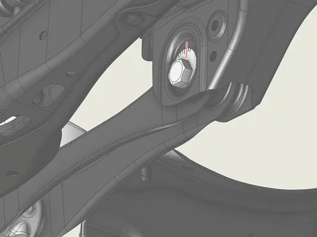
    Note
    Align the center of the plate scale with the guideline when installing bolt and nut.
    Suspension System — Rear Suspension System - Multi Link / Rear Assist Arm / Removal and Installation / Installation illustration
  2. Check the alignment. (Refer to Alignment - "Repair Procedures")

Rear Assist Arm Inspection

Inspection

  1. Check the bushing (A) for wear and aging.
    Suspension System — Rear Suspension System - Multi Link / Rear Assist Arm / Inspection illustration
  2. Check the rear assist arm for bent or damage.
  3. Check all bolts.

Trailing Arm Components and Components Location

Component and Component Location

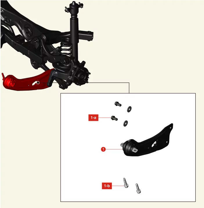
Suspension System — Rear Suspension System - Multi Link / Trailing Arm / Components and Components Location / Component and Component Location illustration
1. Trailing Arm
1-a. 137.3 - 157 N·m
1-b. 98.1 - 118 N·m

Trailing Arm Removal and Installation

Removal

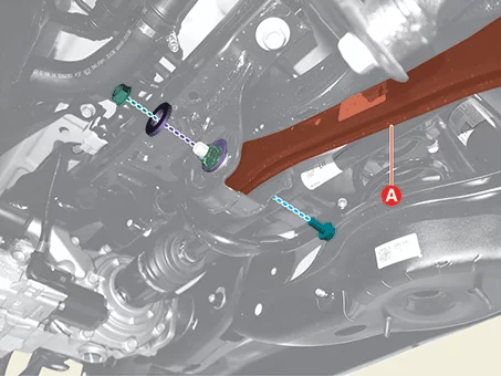
  1. Remove the rear wheel and tires. (Refer to Tires/Wheels - "Wheel")
  2. Remove the trailing arm bolts (A), washers (B), and EPB wire bracket nut (C).
    Tightening torque : (A) : 137.3 - 157 N·m (C) : 8.8 - 13,7 N·m
    Suspension System — Rear Suspension System - Multi Link / Trailing Arm / Removal and Installation / Removal illustration
  3. Remove the trailing arm after removing the bolts (A).

    Tightening torque : 98.1 - 118 N·m

    Suspension System — Rear Suspension System - Multi Link / Trailing Arm / Removal and Installation / Removal illustration

Installation

  1. Install in reverse order of removal.
  2. Check the alignment. (Refer to Alignment - "Repair Procedures")

Trailing Arm Inspection

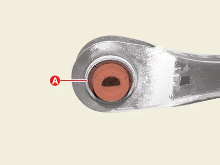
Inspection

  1. Check the bushing for wear and aging.
  2. Check the trailing arm for bent or damage.
  3. Check all bolts and nuts.

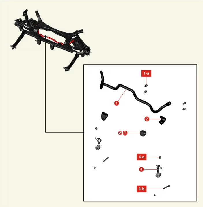
Rear Stabilizer Bar Components and Components Location

Component and Component Location

Suspension System — Rear Suspension System - Multi Link / Rear Stabilizer Bar / Components and Components Location / Component and Component Location illustration
1. Rear Stabilizer Bar
1-a. 44.1 - 54 N·m
2. Rear Stabilizer Bar Bracket
3. Rear Stabilizer Bar Bushing
4. Rear Stabilizer Bar Link
4-a. 58.8 - 78 N·m
4-b. 19.6 - 29 N·m

Rear Stabilizer Bar Removal and Installation

Removal

[Rear Stabilizer Bar Link]
  1. Remove the rear stabilizer bar link nuts (A) and bolts (B).

    Tightening torque : 19.6 - 29 N·m

    Suspension System — Rear Suspension System - Multi Link / Rear Stabilizer Bar / Removal and Installation / Removal illustration
    Note
    Be careful not to change the bolt, nut and washer installing position.
    Information
    Fix the bolt and remove or install the nut.
  2. Remove the rear stabilizer bar link (A) after removing the nut.

    Tightening torque : 58.8 - 78 N·m

    Suspension System — Rear Suspension System - Multi Link / Rear Stabilizer Bar / Removal and Installation / Removal illustration
    Note
    • Fix the outer stud using a tool such as a wrench when installing and removing the stabilizer bar link nut.
    • Be careful not to damage the boot of the link.
    • Use a hand tool when removing or installing the rear stabilizer bar link nut.
  3. Remove the rear differential carrier assembly. (Refer to All Wheel Drive (AWD) System - "Differential Carrier Assembly")
  4. Separate the rear stabilizer bar link (A) after removing the nut.

    Tightening torque : 58.8 - 78 N·m

    Suspension System — Rear Suspension System - Multi Link / Rear Stabilizer Bar / Removal and Installation / Removal illustration
    Note
    • Fix the outer stud using a tool such as a wrench when installing and removing the stabilizer bar link nut.
    • Be careful not to damage the boot of the link.
    • Use a hand tool when removing or installing the rear stabilizer bar link nut.
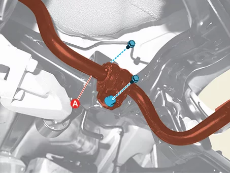
  5. Remove the stabilizer bar (A) after removing the bolts.

    Tightening torque : 44.1 - 54 N·m

    [LH]
    Suspension System — Rear Suspension System - Multi Link / Rear Stabilizer Bar / Removal and Installation / Removal illustration
    [RH]
    Suspension System — Rear Suspension System - Multi Link / Rear Stabilizer Bar / Removal and Installation / Removal illustration
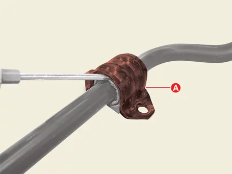
  6. Remove the stabilizer bar bracket (A) using a flat-head screw driver.
    Suspension System — Rear Suspension System - Multi Link / Rear Stabilizer Bar / Removal and Installation / Removal illustration
    Note
    Do not reuse the rear stabilizer bar bracket (A) if it is deformed.
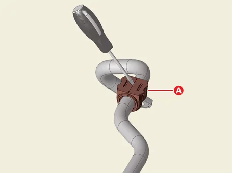
  7. Remove the stabilizer bar bushing (A) using a flat-head screw driver.
    Suspension System — Rear Suspension System - Multi Link / Rear Stabilizer Bar / Removal and Installation / Removal illustration
    Note
    Do not reuse the rear stabilizer bar bushing (A).
    Information
    When replacing the rear stabilizer bar bushing (A), lubricate it for better installation.
[Rear Stabilizer Bar]

Installation

  1. Install in reverse order of removal.
  2. Check the alignment. (Refer to Alignment - "Repair Procedures")

Rear Stabilizer Bar Inspection

Inspection

  1. Check the rear stabilizer bar bushing for damage.
  2. Check the rear stabilizer bar link ball joint for damage.
  3. Check all bolts and nuts.

Rear Cross Member Components and Components Location

Component and Component Location

Suspension System — Rear Suspension System - Multi Link / Rear Cross Member / Components and Components Location / Component and Component Location illustration
1. Rear Cross Member
1-a. 176.5 - 196 N·m
1-b. 176.5 - 196 N·m

Rear Cross Member Removal and Installation

Removal

Warning
If a transmission jack is used with a two-post lift, do not lift the vehicle too much. The center gravity of the vehicle may change and fall.
  1. Remove the rear differential carrier assembly. (Refer to All Wheel Drive (AWD) System - "Differential Carrier Assembly")
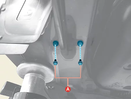
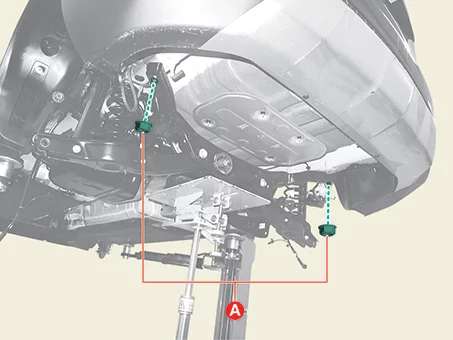
  2. Separate the rear shock absorbers (A) after removing the bolts and washers.

    Tightening torque : 58.8 - 74 N·m

    Suspension System — Rear Suspension System - Multi Link / Rear Cross Member / Removal and Installation / Removal illustration
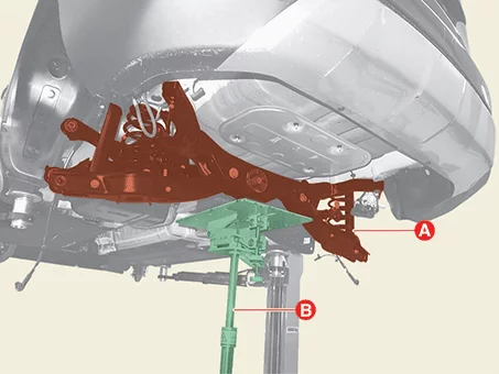
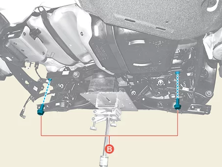
  3. Support the rear cross member (A) with a suitable tool such as the transmission jack (B).
    Suspension System — Rear Suspension System - Multi Link / Rear Cross Member / Removal and Installation / Removal illustration
  4. Remove the nuts (A) and bolts (B), and then lower the jack to remove the rear cross member.

    Tightening torque : 176.5 - 196 N·m

    Suspension System — Rear Suspension System - Multi Link / Rear Cross Member / Removal and Installation / Removal illustration
    Suspension System — Rear Suspension System - Multi Link / Rear Cross Member / Removal and Installation / Removal illustration
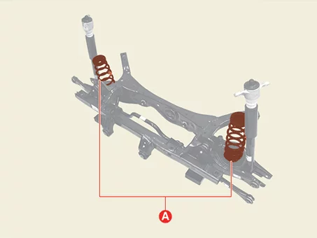
  5. Remove the rear coil spring (A).
    Suspension System — Rear Suspension System - Multi Link / Rear Cross Member / Removal and Installation / Removal illustration
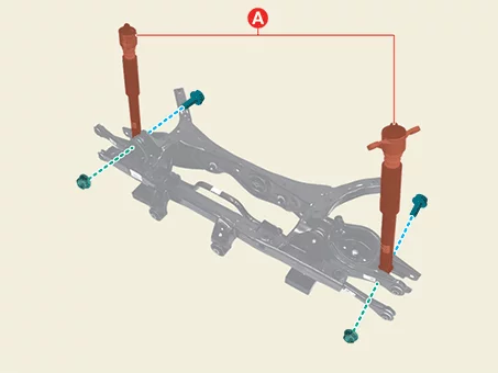
  6. Remove the rear shock absorbers (A) after removing the bolts and nuts.

    Tightening torque : 98.1 - 118 N·m

    Suspension System — Rear Suspension System - Multi Link / Rear Cross Member / Removal and Installation / Removal illustration
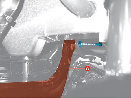
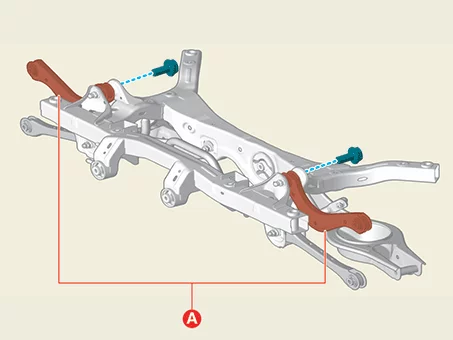
  7. Remove the rear upper arm (A) after removing the bolt.

    Tightening torque : 137.3 - 157 N·m

    Suspension System — Rear Suspension System - Multi Link / Rear Cross Member / Removal and Installation / Removal illustration
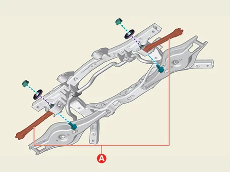
  8. Remove the rear assist arm (A) after removing the bolt, nut, and plate.

    Tightening torque : 107.9 - 118 N·m

    Suspension System — Rear Suspension System - Multi Link / Rear Cross Member / Removal and Installation / Removal illustration
  9. Remove the rear lower arm (A) after removing the bolt, nut, and plate.
    Tightening torque : (B) : 19.6 - 29 N·m (C) : 107.9 - 118 N·m
    Suspension System — Rear Suspension System - Multi Link / Rear Cross Member / Removal and Installation / Removal illustration
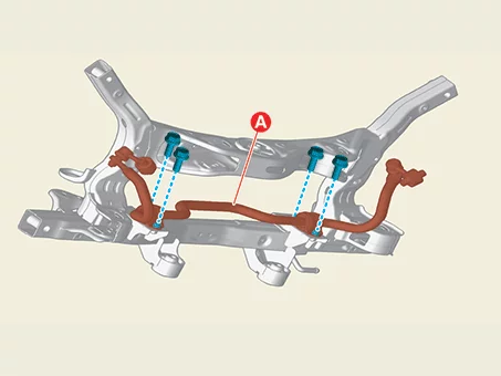
  10. Remove the stabilizer bar (A) after removing the bolts.

    Tightening torque : 44.1 - 54 N·m

    Suspension System — Rear Suspension System - Multi Link / Rear Cross Member / Removal and Installation / Removal illustration

Installation

  1. Install in reverse order of removal.
    Note
    Align the center of the plate scale with the guideline when installing bolt and nut. [Rear Assist Arm]
    Suspension System — Rear Suspension System - Multi Link / Rear Cross Member / Removal and Installation / Installation illustration
    [Rear Lower Arm]
    Suspension System — Rear Suspension System - Multi Link / Rear Cross Member / Removal and Installation / Installation illustration
  2. Check the alignment. (Refer to Alignment - "Repair Procedures")

Rear Cross Member Inspection

Inspection

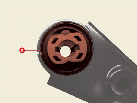
  1. Check the bushing for aging or wearing.
    Suspension System — Rear Suspension System - Multi Link / Rear Cross Member / Inspection illustration
  2. Check all bolts and nuts.