Suspension System
Front Suspension System
In this manual: Suspension System
44steps
~264min
4/5difficulty
Done 0 of 44
Contents:
Components and Components Location
Component
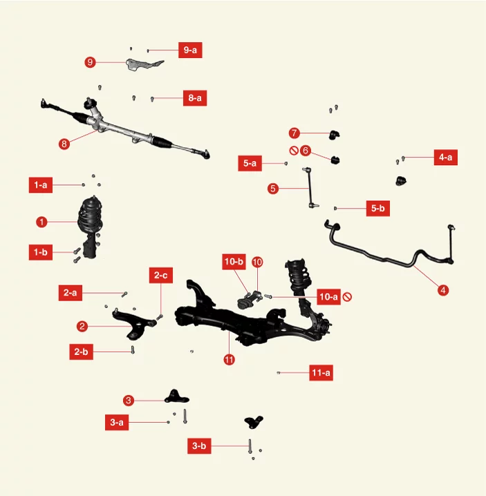
| 1. Front Strut Assembly 1-a. 53.9 - 74 N·m 1-b. 137.3 - 157 N·m 2. Front Lower Arm 2-a. 58.8 - 71 N·m 2-b. 117.7 - 137 N·m 2-c. 156.9 - 176 N·m 3. Front Sub Frame Stay 3-a. 44.1 - 59 N·m 3-b. 176.5 - 196 N·m 4. Front Stabilizer Bar 4-a. 49.0 - 64 N·m 5. Front Stabilizer Bar Link 5-a. 98.1 - 118 N·m 5-b. 98.1 - 118 N·m |
6. Front Stabilizer Bar Bushing 7. Front Stabilizer Bar Bracket 8. Steering Gear Box 8-a. 88.3 - 108 N·m 9. Steering Gear Box Heat Protector 9-a. 7.8 - 11,8 N·m 10. Roll Rod Bracket 10-a. 107.9 - 128 N·m 10-b. 49.0 - 64 N·m 11. Front Sub Frame 11-a. 176.5 - 196 N·m |
Front Strut Assembly Components and Components Location
Component
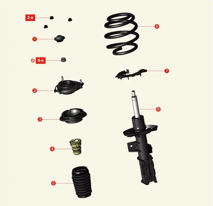
| 1. Insulator Cap 2. Insulator Assembly 2-a. 53.9 - 74 N·m 3. Strut Bearing 4. Bumper Stopper |
5. Dust Cover 6. Coil Spring 7. Spring Lower Pad 8. Strut Assembly 8-a. 98.1 - 108 N·m |
Front Strut Assembly Removal and Installation
Removal
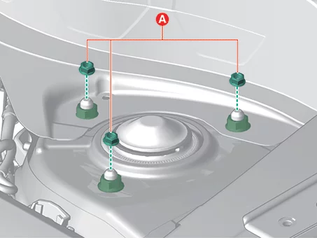
- Remove the front strut upper nuts (A).
Tightening torque : 53.9 - 74 N·m
- Remove the front wheel and tires. (Refer to Tires/Wheels - "Wheel")
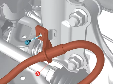
- Remove the bolt, and then separate the brake hose bracket (A).
Tightening torque : 8.8 - 13,7 N·m
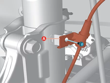
- Separate the front wheel speed sensor wire bracket (A) after removing the bolt.
Tightening torque : 6.9 - 10,8 N·m
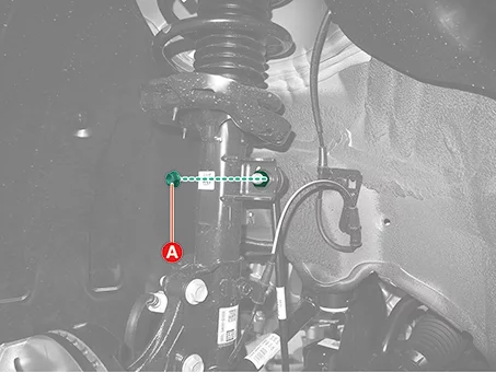
- Remove the stabilizer bar link (A) from the front strut assembly after removing the nut.
Tightening torque : 98.1 - 118 N·m

- Fix the outer stud (A) using a tool such as a wrench when installing and removing the stabilizer bar link nut.

- Be careful not to damage the boot of the link.
- Use only a hand tool when removing or installing the stabilizer bar link nut.
- Fix the outer stud (A) using a tool such as a wrench when installing and removing the stabilizer bar link nut.
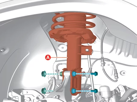
- Remove the front strut assembly (A) from the front axle after removing the bolts and nuts.
Tightening torque : 137.3 - 157 N·m
Installation
- Install in reverse order of removal.
Pre-tighten the front strut upper nuts and put the vehicle down on the ground and tighten the front strut upper nuts to tightening torque.
Front Strut Assembly Disassembly
Special Service Tool
| Tool Name / Number | Illustration | Description |
| Shock absorber lock nut remover. 09546 - 3X100 |
 |
Used for removal or installing of front strut lock nut. |
Disassembly
- Remove the insulator cap (A).

- Compress the coil spring slightly until it is tensioned using the spring compressor (A).
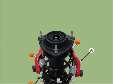
Protect the coil spring when compressing using rubber such as plastic hose, etc to prevent the damage.
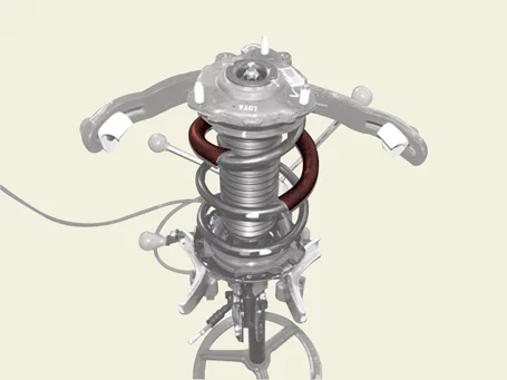
Be careful not to coil spring bounce out from the coil spring, injury can occur.
- Remove the self locking nut using SST (09546 - 3X100).
Tightening torque : 98.1 - 108 N·m

Do not reuse the self locking nut. - Disassemble the front strut assembly.
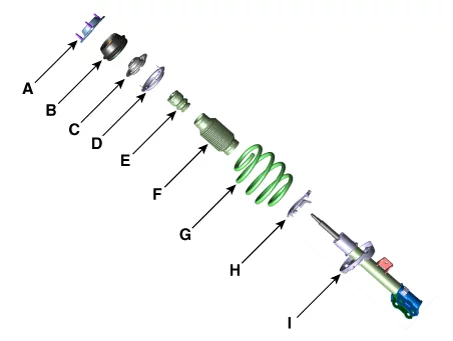
Item Name Item Name A Insulator assembly F Dust cover B Strut bearing assembly G Coil spring C Upper pad seat assembly H Spring lower pad D Upper pad I Strut assembly E Bumper stopper
Front Strut Assembly Inspection
Inspection
- Check the strut insulator bearing for wear and damage.
- Check the rubber parts for damage and deterioration.
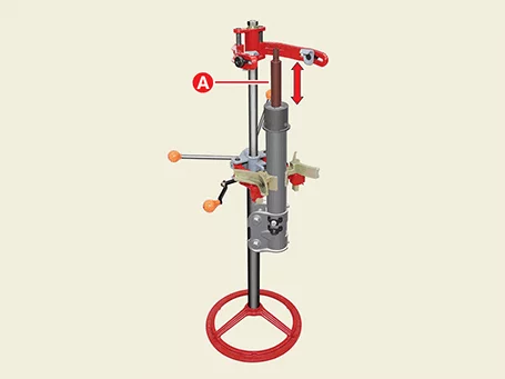
- Compress and extend the piston rod (A) and check that there is no abnormal resistance or unusual sound during operation.
Disposal
- Fully extend the strut rod.
- Drill a hole on the A section to remove gas from the cylinder.
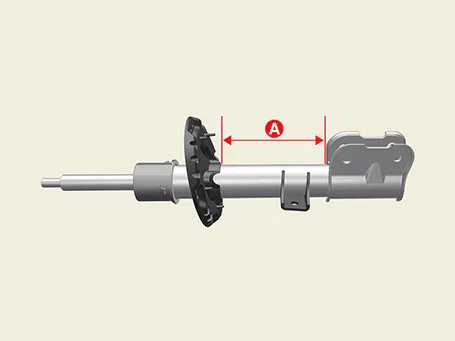
The gas coming out is harmless, but be careful of debris that may fly when drilling.
Front Strut Assembly Reassembly
Special Service Tool
| Tool Name / Number | Illustration | Description |
| Shock absorber lock nut remover. 09546 - 3X100 |
|
Used for removal or installing of front strut lock nut. |
Reassembly
- Reassemble the front strut assembly.
Item Name Item Name A Insulator assembly F Dust cover B Strut bearing assembly G Coil spring C Upper pad seat assembly H Spring lower pad D Upper pad I Strut assembly E Bumper stopper - Compress the coil spring slightly until it is tensioned using the spring compressor (A).
Protect the coil spring when compressing using rubber such as plastic hose, etc to prevent the damage.
Be careful not to coil spring bounce out from the coil spring, injury can occur. - Install the self locking nut using SST (09546 - 3X100).
Tightening torque : 98.1 - 108 N·m
Do not reuse the self locking nut. - Install the insulator cap (A).
Front Lower Arm Components and Components Location
Component
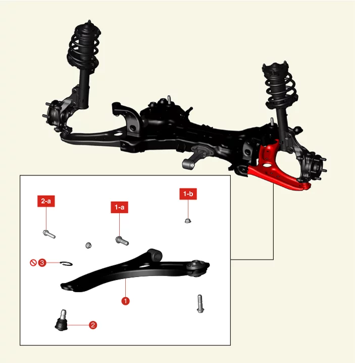
| 1. Front Lower Arm Assembly 1-a. 156.9 - 176 N·m 1-b. 117.7 - 137 N·m |
2. Front Lower Arm Ball Joint 2-a. 58.8 - 71 N·m 3. Snap Ring |
Front Lower Arm Removal and Installation
Special Service Tool
| Tool Name / Number | Illustration | Description |
| Ball joint puller 0K545 - A9100 |
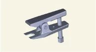 |
Used for removal of front lower arm ball joint |
Removal
- Remove the front wheel and tires. (Refer to Tires/Wheels - "Wheel")
- Remove the engine room under cover. G 1.6 T-GDI GAMMA II (Refer to Engine Mechanical System - "Engine Room Under Cover") G 2.0 MPI NU (Refer to Engine Mechanical System - "Engine Room Under Cover")
- Separate the lower arm ball joint from the front axle.
- Remove the lower arm nut (A) and bolt (B).
Tightening torque : 58.8 - 71 N·m
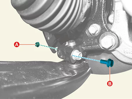
Fix the lower arm ball joint bolt when removing or installing the nut.- Do not reuse the split pin.
- Be careful not to change the bolt, nut and washer installing position.
- Install the support bolt to the lower arm ball joint mounting hole, and then rotate the bolts (A).

Use the support bolt (A) of the SST (0K545 - A9100).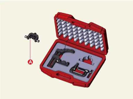
- Place the support body (A) between the lower arm and the front axle (B).
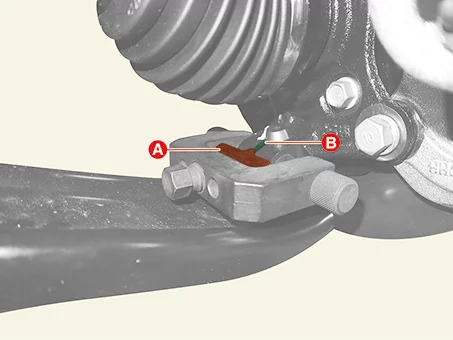
- Rotate the bolt (A) clockwise, and then insert the support body (B) to broaden the gap.
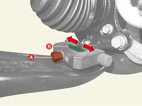
- Install the main body (A) between the front strut assembly and front lower arm.
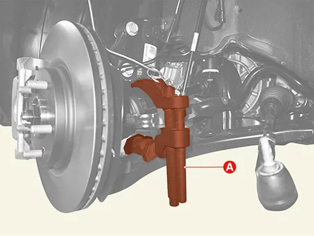
Use the main body (A) of the SST (0K545 - A9100).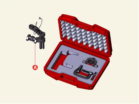
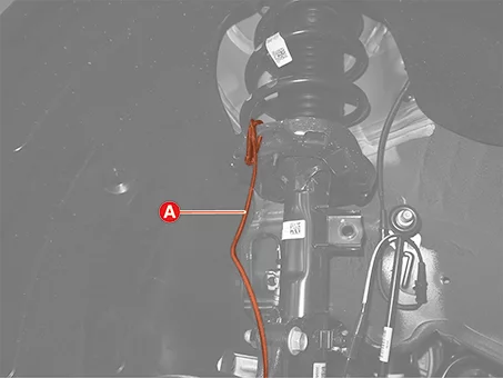
- Secure the main body with the wire (A) to prevent it from falling.
- Install the C-clamp (A) by turning the handle (B) to prevent the main body from slipping.
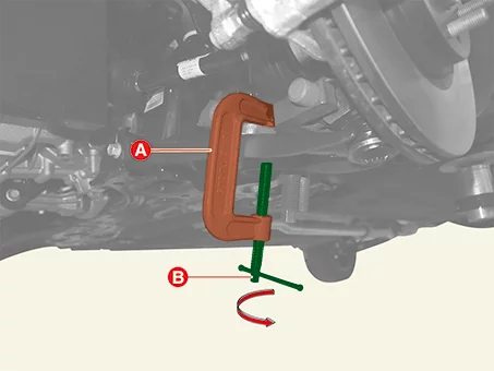
Use the C-clamp (A) of the SST (0K545 - A9100).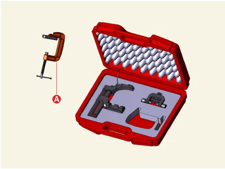
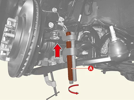
- Tighten the bolt (A), and then separate the front lower arm from the front axle.
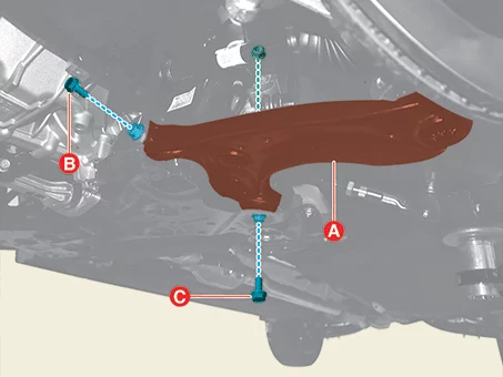
- Remove the lower arm nut (A) and bolt (B).
- Remove the front lower arm (A) after removing the bolt and nut.
Tightening torque : (B) : 117.7 - 137 N·m (C) : 156.9 - 176 N·m
Installation
- Install in reverse order of removal.
- Check the alignment. (Refer to Alignment - "Repair Procedures")
Front Lower Arm Inspection
Inspection
- Check the bushing for wear or aging.
- Check the lower arm for bent or damaged.
- Check all bolts.
- Check the ball joint rotation torque. If there is an abnormality, replace the ball joint.
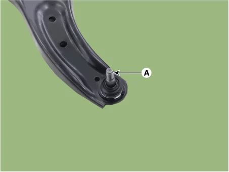
- Check the ball stud (A) axial free play, In case of any free play exist, replace the ball joint (B).

Front Lower Arm Replacement
Replacement
- Remove the front lower arm. (Refer to Front Suspension System - "Front Lower Arm")
- Remove the snap ring (A).
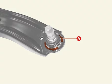
Do not reuse snap ring. - Remove the front lower arm ball joint.
- Place the front lower arm (A) and the suitable adaptor (B).
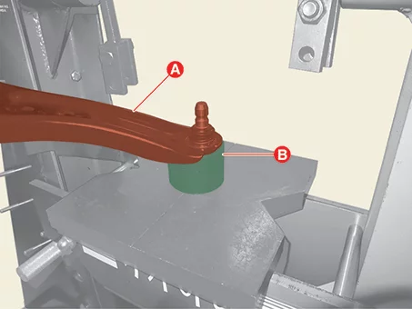
- Remove the front lower arm ball joint (B) by using the machine press (A).
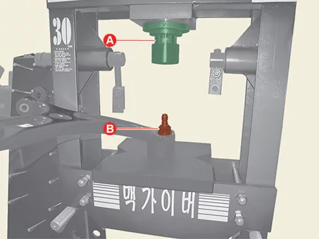
- Before pressing the front lower arm ball joint using a machine press, make sure that the joint is firmly seated.
- Wear safety glasses while using the machine press.
- Do not touch anything within the operating range during machine press operations.
- Place the front lower arm (A) and the suitable adaptor (B).
- Install the front lower arm ball joint.
- Place the new lower arm ball joint (A) on the suitable adaptor (B).
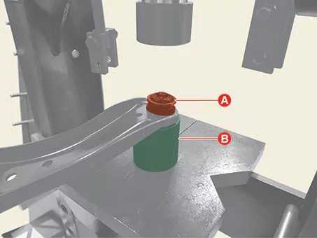
- Install the front lower arm ball joint (B) by using the machine press (A).
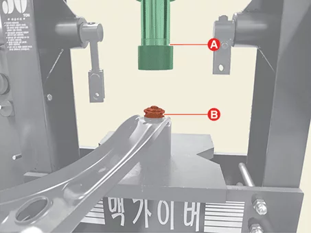
- Before pressing the front lower arm ball joint using a machine press, make sure that the joint is firmly seated.
- Wear safety glasses while using the machine press.
- Do not touch anything within the operating range during machine press operations.
- Place the new lower arm ball joint (A) on the suitable adaptor (B).
- Install the snap ring (A).
Do not reuse the snap ring.
Front Lower Arm Replacement - Lower Arm 'G' Bushing
Special Service Tool
| Tool Name / Number | Illustration | Description |
| Lower arm 'G' bushing replacement tool 09545 - AL100 |
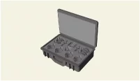 |
Used for replacement of the lower arm 'G' bushing |
Replacement - Lower Arm 'G' Bushing
|
- Replace the lower arm 'G' bushing by using the SST (09545 - AL100).
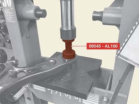
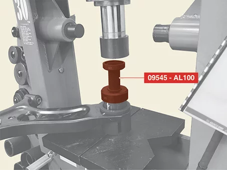
Refer to the enclosed manual for detailed usage instructions.- Wear personal protective equipment during press operation.
- When the press is in operation, ensure that no part of the body comes into contact within the operating range.
- Due to the risk of injury from falling tools and parts, before operating the press, ensure that all tools and components are securely positioned in their proper places.
- Lubricate the bushings and mounting surface with grease during the operation.
- Measure the void spacing (A), (B) to ensure that the bushing can be properly installed in the correct direction.
(A) : Ball joint side (B) : Opposite side
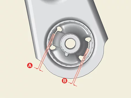
- Refer to the enclosed manual for void spacing specifications for each vehicle model.
- There may be no difference in void spacing for used bushing due to wear.
- Be careful not to install the bushing at the incorrect angle.
Installaion angle (A) : Angle formed counterclockwise from 'A' bushing (B) and 'G' bushing (C) reference
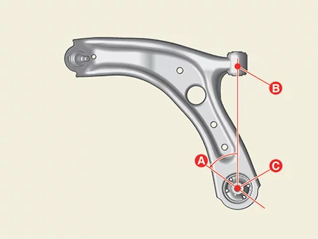
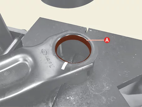
Refer to the enclosed manual for installation angle specifications for each vehicle model. - Clean the bushing mounting surface (A) from any foreign substances using a clean cloth or similar material when installing.
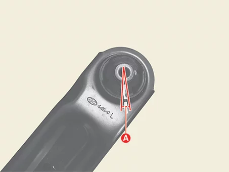
- Ensure that the marking angle (A) of the bushing and the lower arm does not deviate from the reference value.
Reference Value : ± 3°
- If excessive pressure is applied after installation is complete, it may result in damage to the components and tools.
Front Stabilizer Bar Components and Components Location
Component
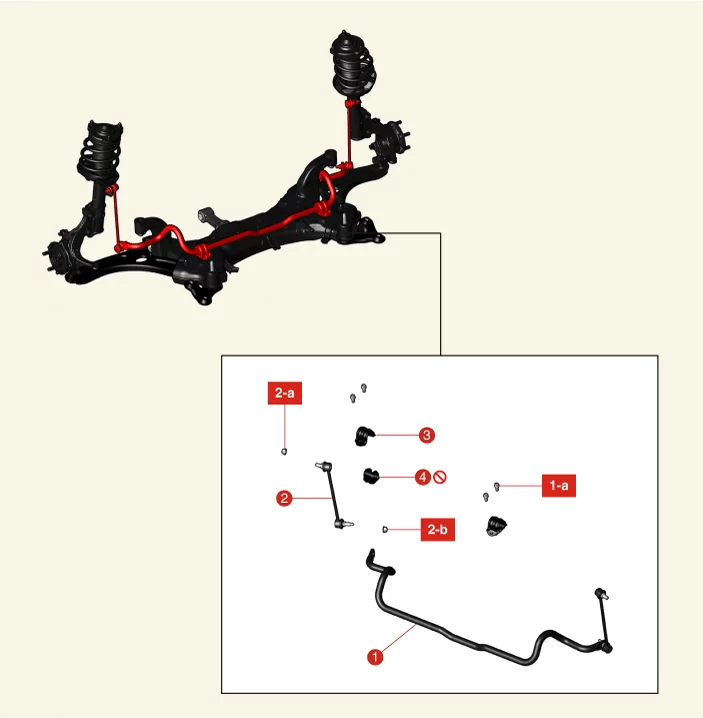
| 1. Front Stabilizer Bar 1-a. 49.0 - 64 N·m 2. Front Stabilizer Bar Link 2-a. 98.1 - 118 N·m 2-b. 98.1 - 118 N·m |
3. Front Stabilizer Bar Bracekt 4. Front Stabilizer Bar Bushing |
Front Stabilizer Bar Removal and Installation
Removal
[Front Stabilizer Bar Link]- Remove the front wheel and tires. (Refer to Tires/Wheels - "Wheel")
- Separate the front stabilizer bar link after removing the nut (A).
Tightening torque : 98.1 - 118 N·m
- Fix the outer stud (A) using a tool such as a wrench when installing and removing the stabilizer bar link nut.
- Be careful not to damage the boot of the link.
- Use only a hand tool when removing or installing the stabilizer bar link nut.
- Fix the outer stud (A) using a tool such as a wrench when installing and removing the stabilizer bar link nut.
- Remove the front stabilizer bar link (A) after removing the nut.
Tightening torque : 98.1 - 118 N·m
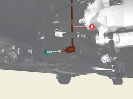
- Fix the outer stud (A) using a tool such as a wrench when installing and removing the stabilizer bar link nut.
- Be careful not to damage the boot of the link.
- Use only a hand tool when removing or installing the stabilizer bar link nut.
- Fix the outer stud (A) using a tool such as a wrench when installing and removing the stabilizer bar link nut.
- Remove the front sub-frame. (Refer to Suspension System - "Front Sub Frame")
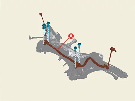
- Remove the front stabilizer bar (A) after removing the bolts.
Tightening torque : 49.0 - 64 N·m
- Remove the front stabilizer bar bracket (A) using a flat-head screwdriver.
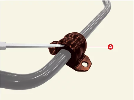
Do not reuse the damaged bracket (A) when installing and removing. - Remove the front stabilizer bar bushing (A) using a flat-head screw driver.
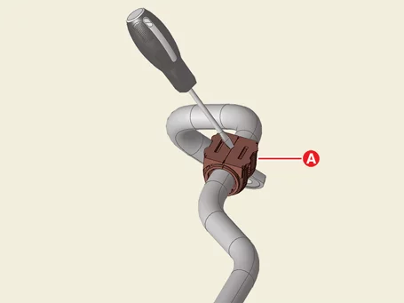
Do not reuse the front stabilizer bar bushing (A).
When replacing the front stabilizer bar bushing (A), lubricate it for better installation.
Installation
- Install in reverse order of removal.
Front Stabilizer Bar Inspection
Inspection
- Check the stabilizer bar bushing for damage.
- Check the stabilizer bar link ball joint for damage.
Front Sub Frame Removal and Installation ➤
Was this page helpful?