Suspension System
Components and Components Location
In this manual: Suspension System
55steps
~330min
4/5difficulty
Done 0 of 55
Contents:
Components and Components Location
Component
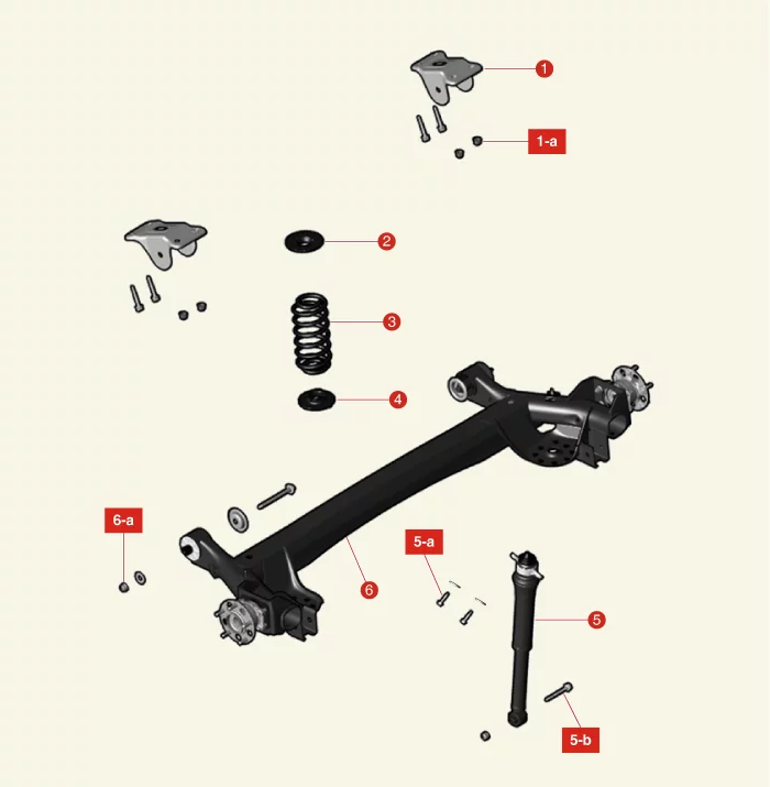
| 1. Rear Torsion Beam Axle Stay 1-a. 98.1 - 118 N·m 2. Rear Coil Spring Upper Pad 3. Rear Coil Spring 4. Rear Coil Spring Lower Pad |
5. Rear Shock Absorber 5-a. 58.8 - 74 N·m 5-b. 98.1 - 118 N·m 6. Rear Torsion Beam Axle 6-a. 137.3 - 157 N·m |
Rear Shock Absorber Components and Components Location
Component and Component Location
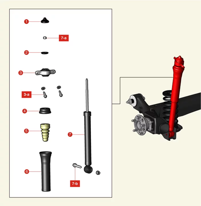
| 1. Insulator cap 2. Retainer 3. Insulator 3-a. 58.8 - 74 N·m |
4. Retainer Cup 5. Bumper Rubber 6. Dust Cover 7. Shock Absorber Assembly 7-a. 21.6 - 29 N·m 7-b. 98.1 - 118 N·m |
Rear Shock Absorber Removal and Installation
Removal
- Remove the rear wheel and tires. (Refer to Tires/Wheels - "Wheel")
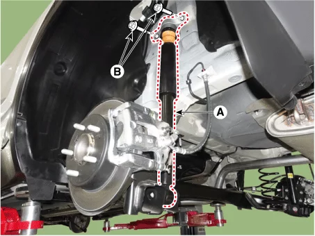
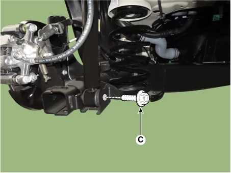
- Remove the rear shock absorber (A) after removing the bolts (B), and (C).
Tightening torque : (B) : 58.8 - 74 N·m (C) : 98.1 - 118 N·m
Installation
- Install in reverse order of removal.
Rear Shock Absorber Disassembly
Special Service Tool
| Tool Name / Number | Illustration | Description |
| Shock absorber lock nut remover. 09546 - 3X100 |
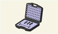 |
Used for removal or installing of rear shock absorber lock nut. |
Disassembly
- Remove the insulator cap (A).
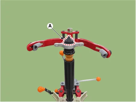
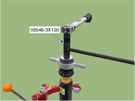
- Remove the self locking nut using the SST (09546 - 3X100).
Tightening torque : 21.6 - 29 N·m
Do not reuse the lock nut.
- Disassemble the rear shock absorber.
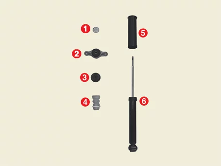
Disassemble the rear shock absorber assembly by the following orders below. 1 → 2 → 3 → 4 → 5 → 6
Number Item Number Item 1 Retainer 4 Bumper rubber 2 Insulator assembly 5 Dust cover 3 Cup 6 Shock absorber assembly
Rear Shock Absorber Inspection
Inspection
- Check the rubber parts for damage or deterioration.
- Check all bolts and nuts.
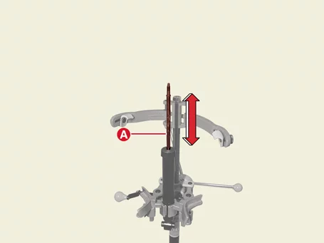
- Repeat compression and tension of the rear shock absorber rod (A) to check for abnormal resistance or noise between operations.
Disposal
- Fully extend the piston rod.
- Drill a hole on the A section to remove gas from the cylinder.
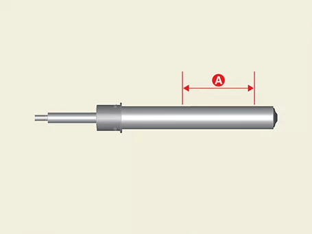
The gas coming out is harmless, but be careful of debris that may fly when drilling.
Rear Shock Absorber Reassembly
Special Service Tool
| Tool Name / Number | Illustration | Description |
| Shock absorber lock nut remover. 09546 - 3X100 |
|
Used for removal or installing of rear shock absorber lock nut. |
Reassembly
- Reassemble the rear shock absorber assembly.
Reassemble the rear shock absorber assembly by the following orders below. 6 → 5 → 4 → 3 → 2 → 1Number Item Number Item 1 Retainer 4 Bumper rubber 2 Insulator assembly 5 Dust cover 3 Cup 6 Shock absorber assembly - Install the self locking nut using the SST (09546 - 3X100).
Tightening torque : 21.6 - 29 N·m
Do not reuse the self locking nut. - Remove the insulator cap (A).
Rear Coil Spring Components and Components Location
Component and Component Location
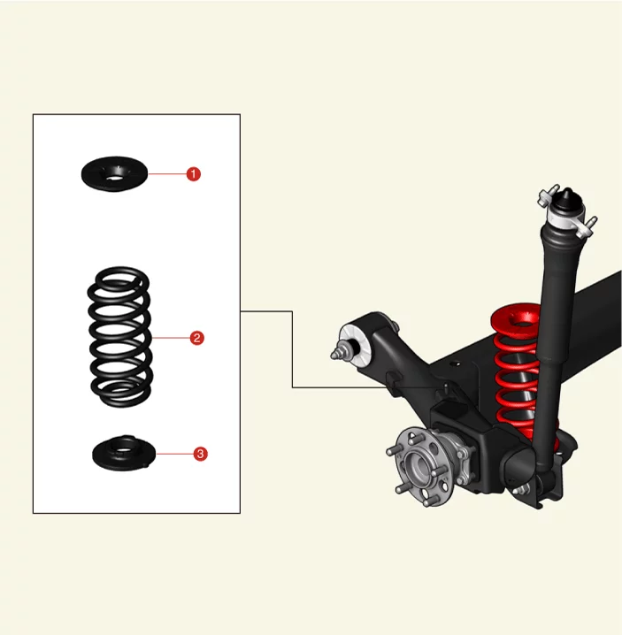
| 1. Coil Spring Upper Pad 2. Coil Spring 3. Coil Spring Lower Pad |
Rear Coil Spring Removal and Installation
Removal
- Remove the rear wheel and tires. (Refer to Tires/Wheels - "Wheel")
- Separate the rear shock absorbers (A) after removing the bolts.
Tightening torque : 98.1 - 118 N·m
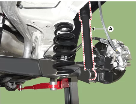
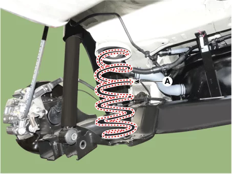
- Remove the coil spring, coil spring upper pad, and lower pad (A).
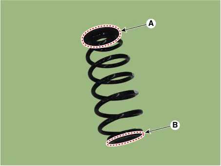
- Remove the coil spring upper pad (A), and lower pad (B).
Installation
- Install in the reverse order of removal.
Rear Coil Spring Inspection
Inspection
- Check the coil spring for cracks or deformation.
- Check the coil spring pad for damage and deformation.
Rear Torsion Beam Axle Removal and Installation
Removal
- Disconnect the battery negative (-) terminal.
- Remove the rear wheel and tires. (Refer to Tires/Wheels - "Wheel")
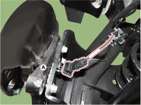
- Disconnect the rear wheel speed sensor connector (A).
- Remove the rear wheel speed sensor wire bracket nuts (A).
Tightening torque : 8.8 - 13,7 N·m

- Remove the rear hub assembly. (Refer to Driveshaft and Axle - "Rear Hub Assembly - 2WD")
- Separate the rear shock absorbers (A) from the coupled torsion beam axle after removing the bolts.
Tightening torque : 98.1 - 118 N·m
- Remove the coil spring (A).
- Support the torsion beam axle (A) with a suitable tool such as the jack.

- Remove the torsion beam axle mounting bolts and nuts (A).
Tightening torque : 137.3 - 157 N·m

- Lower the jack slowly to remove the torsion beam axle (A).
When removing the torsion beam axle (A), pay attention to the interference of the surrounding parts and lower the jack slowly.
Rear Torsion Beam Axle Replacement
Replacement
CTBA (Coupled Torsion Beam Axle) Bushing| Tool Name / Number | Illustration | Description |
| CTBA bushing remover & installer 09551 - AL100 |
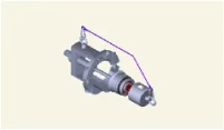 |
Used for removal or installing of the CTBA bushing |
|
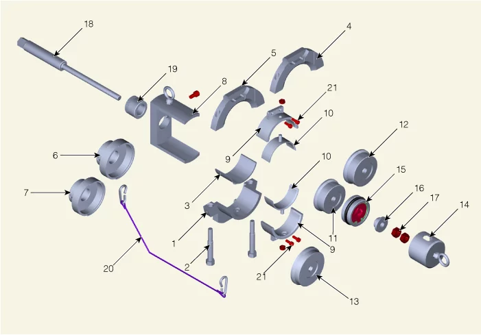
| 1. Beam Clamp A 2. Beam Clamp Bolt 3. Beam Clamp Adaptor 4. Beam Clamp B 5. Beam Clamp C 6. Installer Adaptor A 7. Installer Adaptor B |
8. Beam Clamp Support 9. Bushing Guide A 10. Bushing Guide B 11. Remover Adaptor A 12. Remover Adaptor B 13. Installer Adaptor C 14. Safety Cap |
15. Bearing 16. Bearing Washer 17. Nut 18. Main Bolt 19. Main Nut 20. Safety Wire 21. Bushing Guide Bolt |
- Remove the rear torsion beam axle. (Refer to Rear Suspension System - "Rear Torsion Beam Axle")
- Measure the outer diameter (A) of the CTBA bushing.

- Refer to the following table and prepare the SST according to the size of the bushing outer diameter.
Type 1 : 78.0 mm (3.0708 in.) Type 2 : 84 mm (3.3070 in.)Type Outer Diameter SST Type 1 78 mm (3.0708 in.) 1, 3, 5, 7, 8, 11, 13, 14, 15, 16, 17, 18, 19, 20 Type 2 84 mm (3.3070 in.) 1, 4, 6, 8, 11, 13, 14, 15, 16, 17, 18, 19, 20 - Install the SST[3] (B) to the SST[1] (A) by tightening the nut. [Type 1 Only]
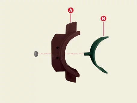
- Pre-install the SST[1] (B) to the SST[5 or 4] (A) by tightening the bolts[2]. Type 1 : SST [5] Type 2 : SST [4]
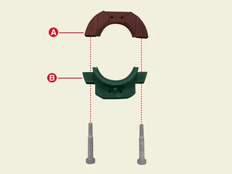
- Install the SST[5 or 4 + 1] (A) to the outside of the bushing. Type 1 : SST [5, 1] Type 2 : SST [4, 1]
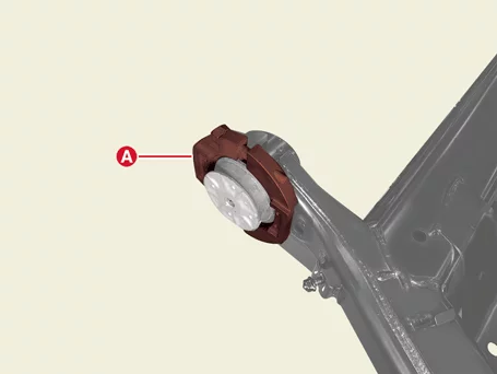
- Install SST [8,19,18] (A) to SST [5 or 4 + 1] by passing through the bushing inner diameter. Type 1 : SST [5, 1] Type 2 : SST [4, 1]

- Install the SST[11] (A) to the SST[18].

- Install the SST[15] (A) to the SST[18].

- Install the SST[16] (A) to the SST[18].

- Install the 2 SST[17] (A) to the SST[18].
Tightening torque : 49 N·m
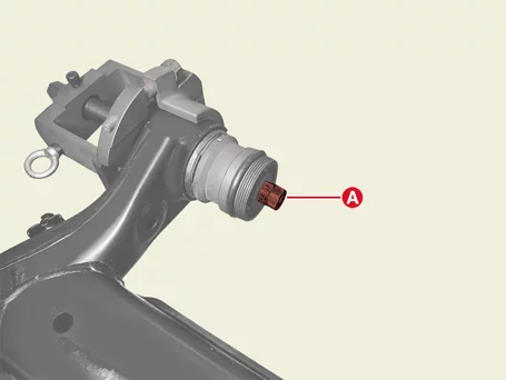
The end of SST[17] (A) and SST[18] should be aligned in straight line. - Install the SST[14] (A).
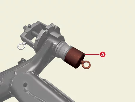
- Install the SST[20] (A) to the 2 hooks as shown as below.
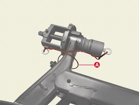
If the SST [20] is not installed properly, injury may occur.
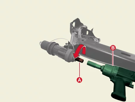
- Rotate the bolt (A) counter clockwise using an impact wrench (B) to remove the bushing.
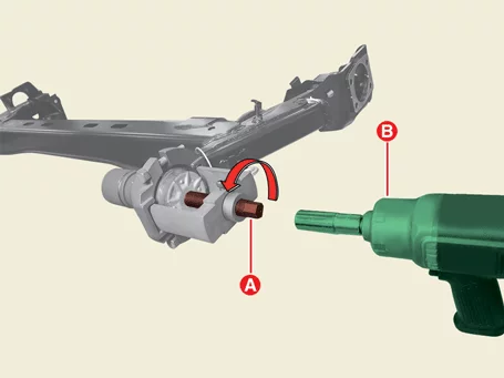
- Remove the SST[20] (A).
- Remove the SST[1, 4 or 5,8,18,19] (A) from the bushing. Remove the SST[1, 4 or 5,8,18,19] (A) from the bushing. Type 1 : SST [5] Type 2 : SST [4]
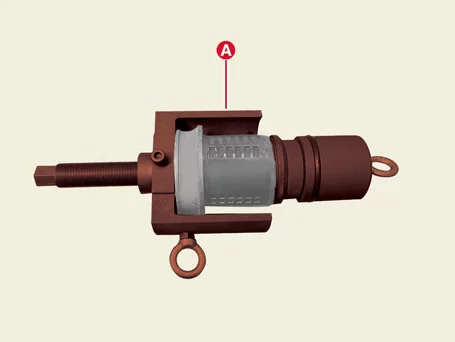
- Install the SST[6 or 7] (A) to the SST[18,19]. Type 1 : SST [7] Type 2 : SST [6]
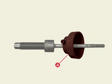
Install the SST[6 or 7] bolt (A) to the SST[19] hole (B).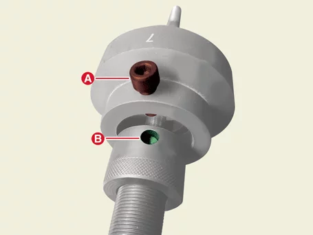
- Install the new bushing (A) to the CTBA.
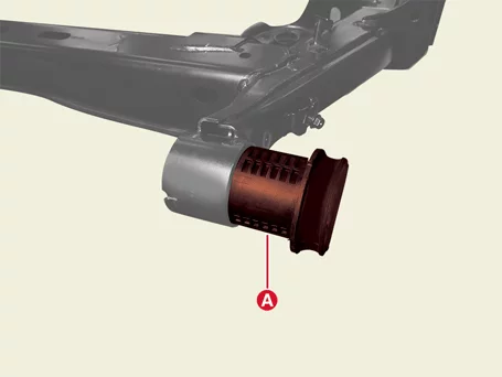
- Install the SST[7,18] (A) by passing through the bushing inner diameter.
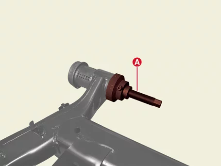
- Install the SST[13] (A) to the SST[18].
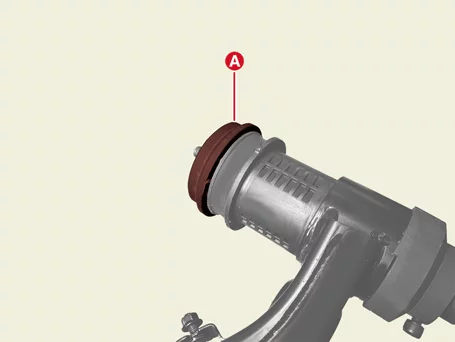
- Install the SST[15] (A) to the SST[18].

- Install the SST[16] (A) to the SST[18].

- Install the 2 SST[17] to the SST[18].
Tightening torque : 49.049.049.49 N·m
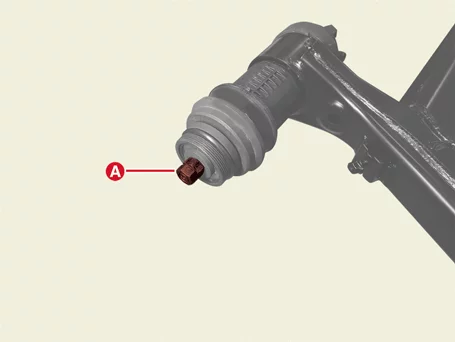
- Install the SST[14] (A).
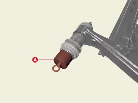
- Install the SST[20] (A) to the 2 hooks as shown as below.
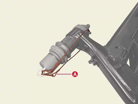
If the SST [20] is not installed properly, injury may occur. - Install the new CTBA bushing by rotating the main bolt (A) counter clockwise using the impact wrench (B).
Install the bushing until there is no gap (A) between the bushing and CTBA.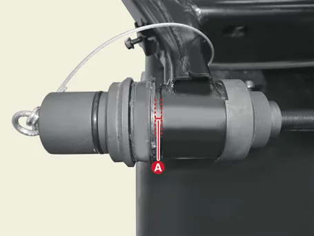
Was this page helpful?