Generator
Specifications
Specification
▷ 13.5 V, 150 A
| Item | Specification |
| Rated Voltage | 13.5 V, 150 A |
| Operating Speed | 0–18,000 rpm |
| Pin | 1 |
| Voltage Regulator | Built-in IC regulator type |
| Regulated Voltage Default (V) [COM Terminal] | 14,39–15,43 [-35°C(31°F)] |
| 14,15–14,95 [25 °C] | |
| 13,23–14,49 [140 °C] | |
| Pulley Type | OAP |

Description and Operation
Description
The AC generator has eight built-in diodes, each of which converts alternating current to direct current.
Therefore, direct current appears at the generator "B" terminal.
In addition, the charging voltage of this generator is controlled by the battery voltage sensing system.
The generator is regulated by the battery voltage sensing system.
The main components of the generator are the rotor, stator, rectifier, capacitor, brushes, bearings, and the drive pulley for the poly-V belt.
The brush holder contains a built-in electronic voltage regulator.

1. Brush 2. Drive belt pulley 3. Rotor 4. Stator
Components and Component Location
Components

| 1. Pulley 2. Front Bracket 3. Front Bearing 4. Bearing Cover 5. Bearing Cover Bolt 6. Rotor 7. Rear Bearing |
8. Rear Bracket 9. Through Bolt 10. Brush Holder Assembly 11. Brush Holder Bolt 12. Rear Cover 13. Nut |
Circuit Diagrams
Wiring Diagram

Repair Procedures
Removal
Turn the ignition switch OFF and disconnect the negative (-) battery terminal.
Remove the drive belt.
(Refer to Engine Mechanical System - "Drive Belt")
Disconnect the generator connector (B) and disconnect the cable (A) from the generator "B" terminal.

Remove the generator lower bolt and upper bolt (A).
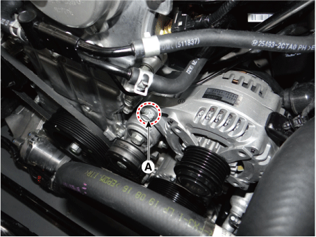
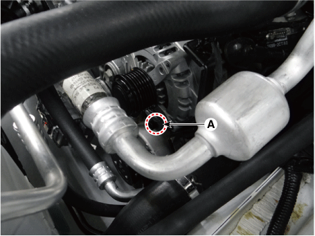
Remove the alternator (A).


Installation
Install in the reverse order of removal.
Install the drive belt.
(Refer to Engine Mechanical System - "Drive Belt")
Test yourself
A quick Kia Stinger CK quiz: every answer comes with an explanation and a link to the manual page.