Engine Control System/Fuel System
DC-DC Converter
In this manual: Engine Control System/Fuel System
7steps
~42min
2/5difficulty
Done 0 of 7
Components and Component Location
Component Location

Circuit Diagrams
Wiring Diagram
[200 W]

[400 W]

Terminal Function
[200 W]

| Pin. | Description | Pin. | Description |
| 1 | Battery Power Input (B+) | 7 | ISG Signal Input |
| 2 | - | 8 | ACC Input |
| 3 | - | 9 | ACC Output |
| 4 | Battery Power Output (B+) | 10 | Ground |
| 5 | - | 11 | - |
| 6 | IGN1 input | ||
[400 W]

| Pin. | Description | Pin. | Description |
| 1 | Battery Power Input (B+) | 7 | Battery Power Input (B+) |
| 2 | - | 8 | Battery Power Output (B+) |
| 3 | Battery Power Output (B+) | 9 | Battery Power Output (B+) |
| 4 | Ground | 10 | Ground |
| 5 | IGN1 input | 11 | ACC Output |
| 6 | ISG Signal Input | 12 | ACC Input |
Repair Procedures
Removal
[200 W]
Turn the ignition switch OFF and disconnect the negative (-) battery terminal.
Remove the glove box housing.
(Refer to Body (Interior and Exterior) - "Glove Box Housing")
Remove the [right] side air duct (A) after loosening the mounting screw.

Remove the DC-DC converter after loosening the mounting bolt (A) and nut (B).


[400 W]
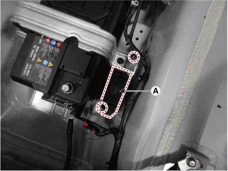
Turn the ignition switch OFF and disconnect the negative (-) battery terminal.
Disconnect the DC/DC converter connector (A).

Remove the DC-DC converter (A) after loosening the mounting nuts.
Installation
Install in the reverse order of removal.
Test yourself
A quick Kia Stinger CK quiz: every answer comes with an explanation and a link to the manual page.
Was this page helpful?