Front Disc Brake
Components and Component Location
Components
[Standard]
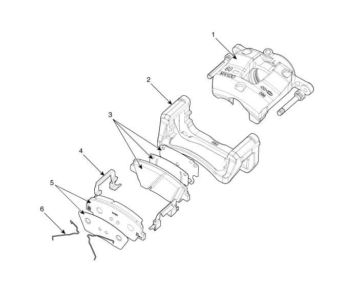
| 1. Caliper Body 2. Brake Pad Shim 3. Inner Brake Pad Assembly [IN] |
4. Retainer 5. Outer Brake Pad Assembly [OUT] 6. Brake Pad Return Spring |
[Brembo]
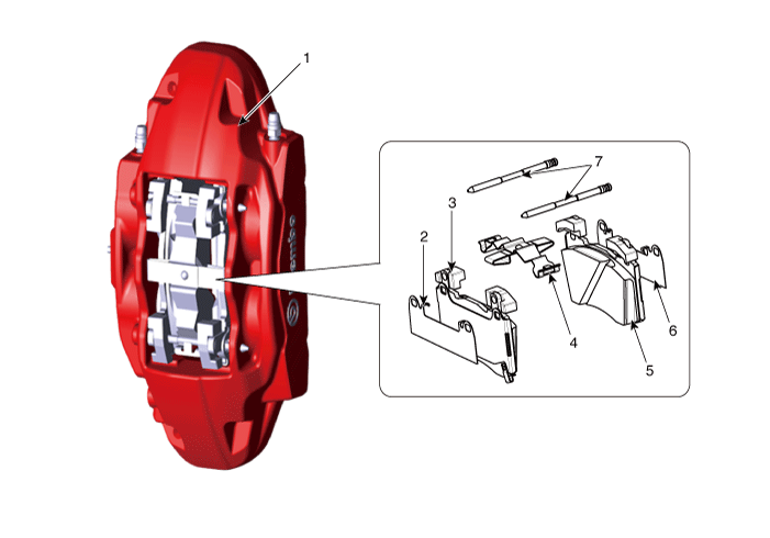
| 1. Caliper Body 2. Brake Pad Cover 3. Brake Pad 4. Retraction Spring |
5. Brake Pad 6. Brake Pad Cover 7. Guide Pin |
Repair Procedures
Removal
[Standard]
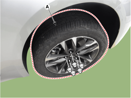
Remove the wheel nuts, front wheel and tire (A) from the front hub.
Tightening torque: 107.9–128 N·m
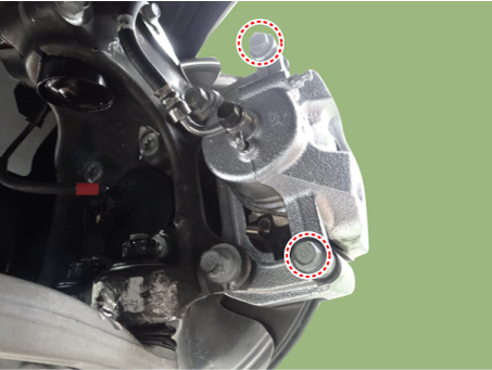
Loosen the caliper guide bolts and remove the brake caliper.
Tightening torque: 21.6–31 N·m
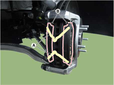
Remove the return spring (A) and brake pad (B).
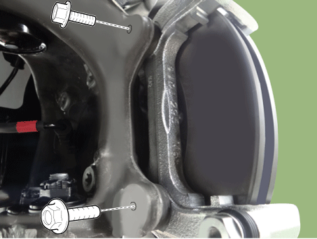
Loosen the brake caliper mounting bolts and remove the brake caliper assembly.
Tightening torque: 78.5–98 N·m
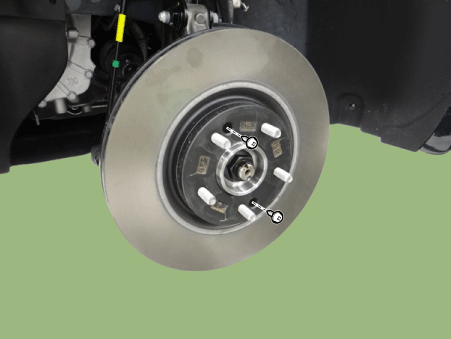
Loosen the brake disc screw and remove the brake disc.
Tightening torque: 4.9–5.9 N·m
Install in the reverse order of removal.
[Brembo]
Remove the wheel nuts, front wheel and tire (A) from the front hub.
Tightening torque: 107.9–128 N·m
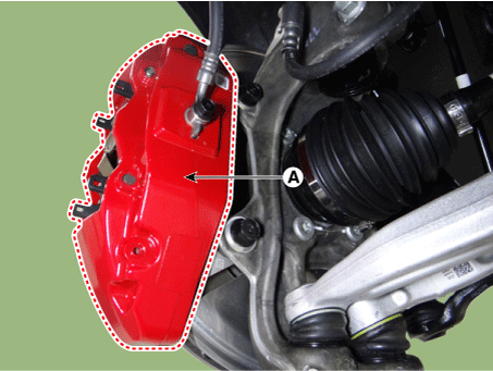
Remove the brake caliper (A).
Tightening torque: 98.1 - 118 N·m
Loosen the brake disc screw and remove the brake disc.
Tightening torque: 4.9–5.9 N·m
Install in the reverse order of removal.
Replacement
[Standard]
Brake Pad
Remove the wheel nuts, front wheel and tire (A) from the front hub.
Tightening torque: 107.9–128 N·m
Loosen the guide pin bolt, then rotate the caliper body upward out of the way.
Tightening torque: 21.6–31 N·m
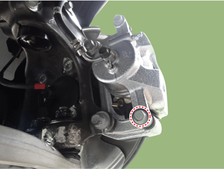
Remove the return spring (A) and brake pad (B).
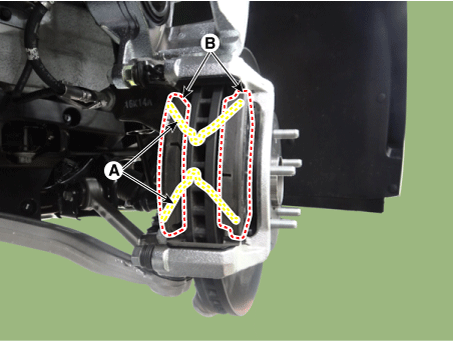
Install in the reverse order of removal.
Use SST (09581-11000) when installing the brake caliper assembly.
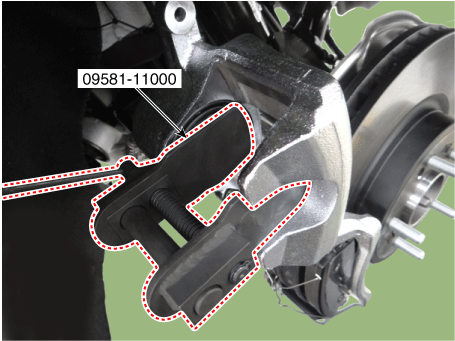
After installation, bleed the brake system.
(Refer to Brake System - "Brake Bleeding Procedures")
[Brembo]
Brake Pad
Remove the wheel nuts, front wheel and tire (A) from the front hub.
Tightening torque: 107.9–128 N·m
Press the guide pin (A) and remove the return spring (B).
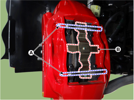
Remove the brake pad.
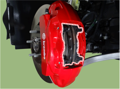
Install in the reverse order of removal.
Use SST (09581-11000) when installing the brake caliper assembly.
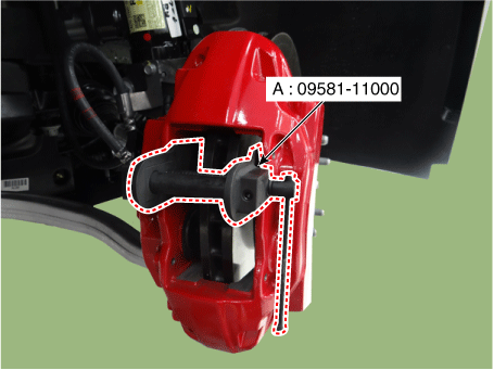
Use SST (09581-11000) when installing the brake caliper assembly.
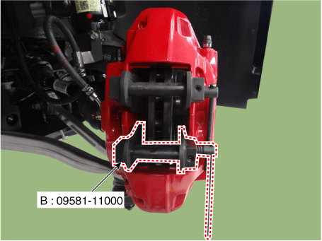
After installation, bleed the brake system.
(Refer to Brake System - "Brake Bleeding Procedures")
Inspection
Inspect Front Brake Disc Thickness
Inspect the brake pads for wear and discoloration.
Inspect the brake disc for damage and cracks.
Remove all rust and contamination from the surface, then measure the disc thickness at 8 points at equal distances (5 mm) from the outer edge of the brake disc.
Front brake disc thickness
- 17 inch Standard: 28.0 mm (1.10 in.)
- 17 inch Service Limit: 26.0 mm (1.02 in.)
- 18 inch Standard: 30 mm (1.18 in.)
- 18 inch Service Limit: 28.0 mm (1.10 in.)
- Deviation: Less than 0.005 mm (0.0002 in.)
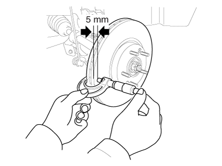
If wear exceeds the service limit, replace the discs and pads as a set, left and right of the vehicle.
Front Brake Pad Inspection
Check pad wear. Measure the pad thickness and replace it if it is less than the specified value.
Pad Thickness
- 17 inch Standard Value: 11.0 mm (0.43 in.)
- 17 inch Service Limit: 2.0 mm (0.08 in.)
- 18 inch Standard Value: 10.6 mm (0.42 in.)
- 18 inch Service Limit: 2.8 mm (0.11 in.)
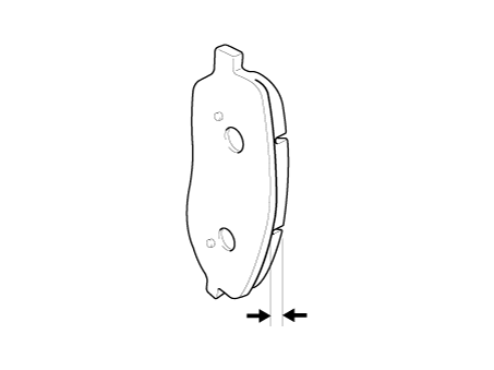
Make sure grease is applied to the sliding contact points, and check the pad and backing plate for damage.
Inspect Front Brake Disc Runout
Position a dial indicator approximately 5 mm (0.2 in) from the outer edge of the brake disc and measure disc runout.
Brake disc runout Limit: 0.04 mm (0.00157 in.) or less (new)
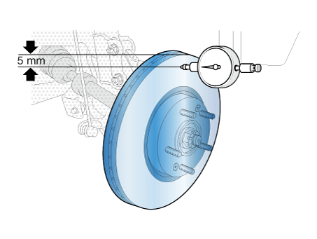
If brake disc runout exceeds the limit, replace the disc, then measure the runout again.
If the runout does not exceed the limit, install the brake disc rotated 180°, then check the brake disc runout again.
If runout cannot be corrected by changing the position of the brake disc, replace the brake disc.
Test yourself
A quick Kia Stinger CK quiz: every answer comes with an explanation and a link to the manual page.