Stop Lamp Switch
Components and Component Location
Components
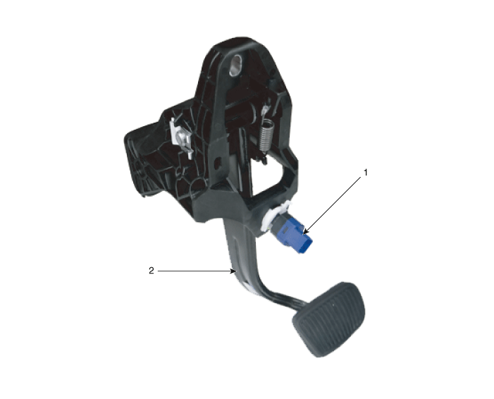
| 1. Stop Lamp Switch | 2. Brake Pedal |
Description and Operation
Operation
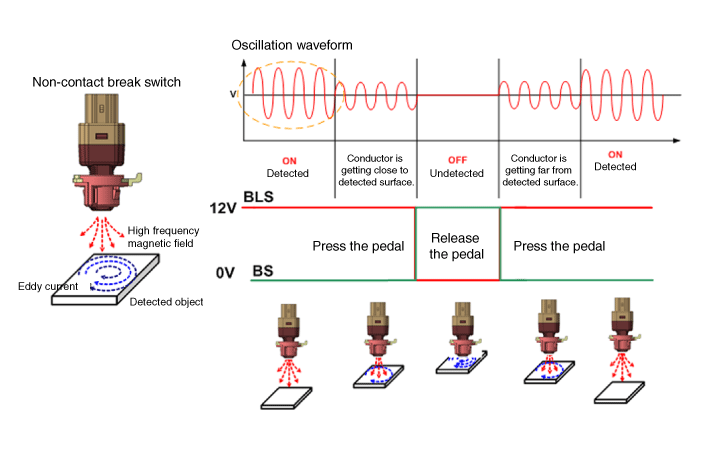
Operating Principle of Inductive Non-Contact Switch
Uses a high-frequency magnetic field and induced current generated by the oscillation (up to the specified voltage) of the coil in the switch.
An eddy current is generated on the metal surface by the self-inductance effect when metal is present in the high-frequency magnetic field.
The generated eddy current weakens the high-frequency magnetic field by the same amount as the magnetic flux change caused by the switch.
ON-OFF is determined by evaluating whether the high-frequency magnetic field is weakened or not (calculates the voltage difference between the metal and the coil).
Circuit Diagrams
Terminal Function
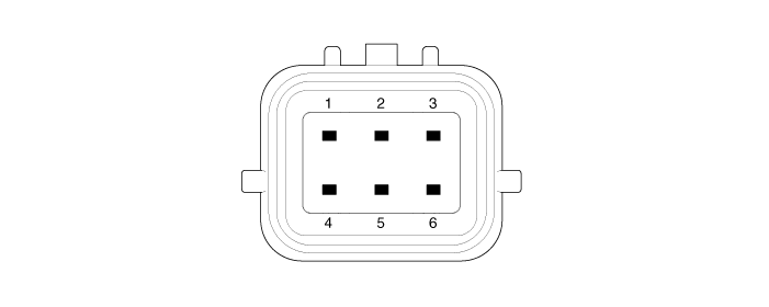
| Pin No. | Description |
| 1 | IGN1 |
| 2 | IBU |
| 3 | - |
| 4 | B+ |
| 5 | Stop Lamp |
| 6 | Ground |
Troubleshooting
Troubleshooting
Component Inspection
Items Cause Symptom Fuse Switch Loose fuse connection, blown fuse DTC: P0504
Symptom: Shift problems, start failure, cruise control cancel function problem, EPB cancel function malfunction, brake light malfunction, ESP OFF lamp ON.
① Check the signal waveform using an oscilloscope on each part while the vehicle is accelerating/braking. (Refer to Brake Light Switch Circuit Inspection Procedure)
② Refer to the applicable part repair procedure if any abnormality is found in the waveform (refer to the repair procedure for the relevant part and replace if necessary)Fuse Relay Loose fuse connection, blown fuse DTC: P0504
Symptom: Shift problems, start failure, cruise control cancel function problem, EPB cancel function malfunction, brake light malfunction, ESP OFF lamp ON.
Stop Lamp Switch Damaged wiring of each component
Incorrect connector connection
Faulty component
DTC: P0504
Symptom: Shift problems, start failure, cruise control cancel function problem, EPB cancel function malfunction, brake light malfunction, ESP OFF lamp ON.
Stop Lamp Electronic
Module (if applicable)DTC: P0504, C2130, C2131
Symptom: Shift problems, start failure, cruise control cancel function problem, EPB cancel function malfunction, brake light malfunction, ESP OFF lamp ON.
Engine Control Module (ECM) DTC: P0504
Symptom: Shift problems, cruise control cancel problem
Body Control Module (BCM) Gear Shifting Concerns
Shift Lock Solenoid Gear Shifting Concerns
Inhibitor Switch Symptom: Shift problems, no-start, cruise control cancel problem, EPB release function problem
Smart Key Unit (SMK) Starting Failure
Electronic Parking Brake (EPB) Symptom: EPB release function problem, ESP OFF indicator illuminated.
ABS/VDC Control Unit (Pressure Sensor) Symptom: ESP OFF lamp illuminated.
Symptom Diagnostics
Symptom Possible Cause Starting Problems Switch fuse, relay fuse, brake light switch, electronic brake light module, ABS/VDC control module, each wire, connector ① Check the signal waveform using an oscilloscope on each part while the vehicle is accelerating/braking. (Refer to Brake Light Switch Circuit Inspection Procedure)
② Refer to the applicable part repair procedure if any abnormality is found in the waveform (refer to the repair procedure for the relevant part and replace if necessary)Gear Shifting Concerns Switch fuse, relay fuse, brake light switch, electronic brake light module, BCM, ECM, inhibitor switch, each wire, connector ESP OFF indicator light is on Switch fuse, relay fuse, brake light switch, electronic brake light module, ABS/VDC control module, each wire, connector P0504 Switch fuse, relay fuse, brake light switch, electronic brake light module, ECM, each wire, connector Stop lamp does not operate Switch fuse, relay fuse, brake light switch, electronic brake light module, wire/connector disconnected Stop lamp always
onStop lamp switch, stop lamp electronic module,
Wiring short circuit, blown fuseStop Lamp Switch System Diagnosis
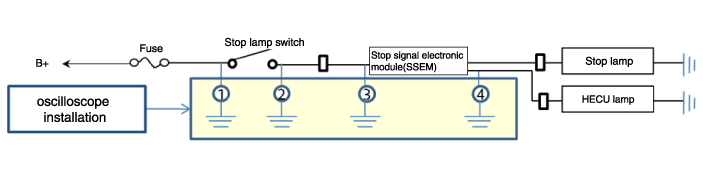
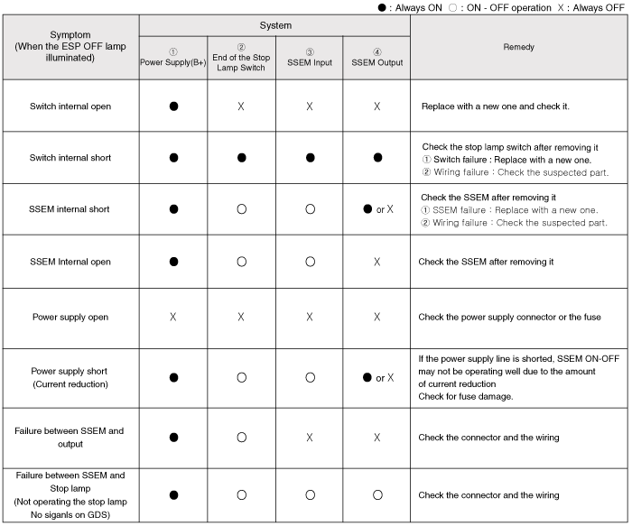
SSEM: Stop Lamp Electronic Module
Refer to the DTC Chart when the applicable DTCs are displayed.
Repair Procedures
Removal
Turn the ignition switch OFF and disconnect the negative (-) battery cable.
Remove the airbag lower panel.
(Refer to Body - "Under Cover Panel")
Remove the knee airbag.
(Refer to Passive Safety System - "Knee Airbag (KAB) Module").
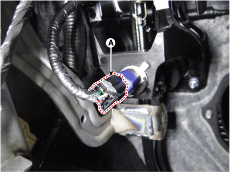
Disconnect the stop lamp switch connector (A).
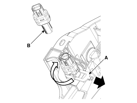
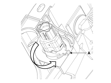
Pull the stopper plate (A) in the direction shown by the arrow, then rotate the brake switch (B) 45° clockwise and remove it.
Inspect the removed stop lamp switch according to the procedures described below.
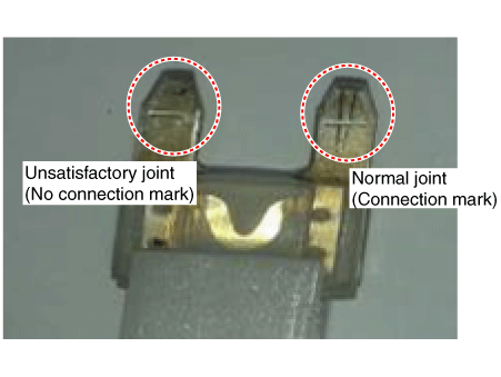
Confirm proper connection with the terminal part.
Confirm that the connector is properly secured and that the connection mark is present.
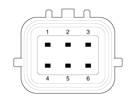
Perform a resistance check of the parts.
Installation
Hold the brake pedal arm and fully insert the brake switch so that the contact part is not visible.
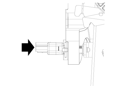
After inserting, rotate the brake switch 45° counterclockwise, then install the stopper plate by pressing it.
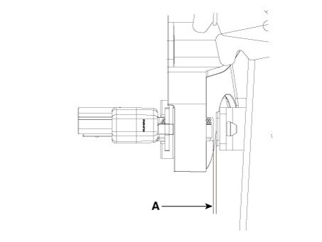
Check the clearance between the stop lamp switch and the bracket.
Stop lamp switch clearance (A): 1.0-2.0 mm (0.04-0.08 in.)
Connect the stop lamp switch connector (A).
Inspection
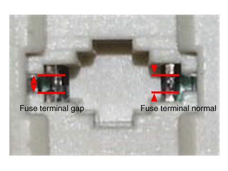
1. Check Fuses
Install a test fuse in place of the switch fuse and the relay fuse part to confirm normal operation.
2. Analyze CAN Data
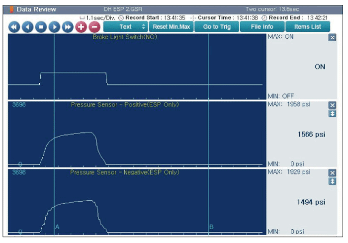
Analyze the KDS data and check the brake switch for proper operation.
Connect the KDS to the self-diagnosis connector.
Turn the ignition switch ON.
Press the brake pedal.
Inspect the "Brake Switch" circuit, which displays the "Sensor Data" in the GDS.
Normal signal pattern: The brake pressure sensor signal value will change according to the brake switch ON/OFF state.
3. Inspect Connector for Each Part
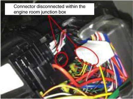
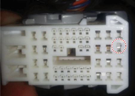
Check each connector for damage, overheated terminals, or incomplete connection.
[Engine Room Junction Box]
[ABS/VDC Control Module]
4. Inspect Lamp Circuit
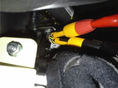
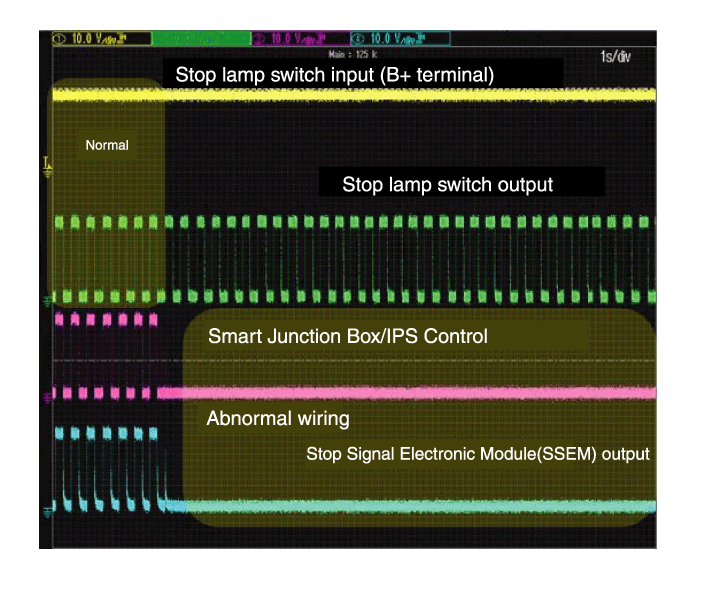
Connect the probe to each terminal wire and check the signal waveform.
[Brake Light Switch Input/Output]
[Oscilloscope Waveform Screen]
Test yourself
A quick Kia Stinger CK quiz: every answer comes with an explanation and a link to the manual page.