Front lower arm
Repair Procedures
Removal
[2WD Side Arm]
Remove the wheel nuts, then remove the front wheel and tire (A) from the hub.
Tightening torque: 107.9–128 N·m

Remove the front wheel guard.
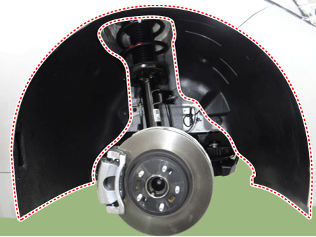
Remove the front stabilizer bar.
(See Suspension System - Front Stabilizer Bar)
Remove the engine room side cover.
D 2.2 R VGT (See Engine Mechanical System - Under Engine Room Cover)
G 2.0 T-GDI THETA II (See Engine Mechanical System - Engine Room). Under Cover")
G 3.3 T-GDI LAMBDA II (See Engine Mechanical System - Engine Room). Under Cover")
Remove the side arm.
Tightening torque: 117.7–132 N·m
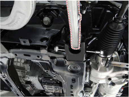
Loosen the lower arm pin (A) and nut (B).
Tightening torque: 88.3–108 N·m

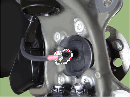
Disconnect the wheel speed sensor connector.
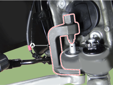
Remove the lower arm using a ball joint remover (A).
Install in the reverse order of removal.
Inspect the front wheel alignment.
(See Suspension System - Alignment)
[AWD Side Arm]
Remove the wheel nuts, then remove the front wheel and tire (A) from the hub.
Tightening torque: 107.9–128 N·m
Remove the engine room side cover.
D 2.2 R VGT (See Engine Mechanical System - Under Engine Room Cover)
G 2.0 T-GDI THETA II (See Engine Mechanical System - Engine Room). Under Cover")
G 3.3 T-GDI LAMBDA II (See Engine Mechanical System - Engine Room). Under Cover")
Loosen the lower arm pin (A) and nut (B).
Tightening torque: 88.3–108 N·m

Remove the lower arm using a ball joint remover (A).

Remove the side arm.
Tightening torque: 117.7–132 N·m
Install in the reverse order of removal.
Inspect the front wheel alignment.
(See Suspension System - Alignment)
[2WD Compression Arm]
Remove the wheel nuts, then remove the front wheel and tire (A) from the hub.
Tightening torque: 107.9–128 N·m
Remove the front wheel guard.
Remove the front stabilizer bar.
(See Suspension System - Front Stabilizer Bar)
Remove the engine room side cover.
D 2.2 R VGT (See Engine Mechanical System - Under Engine Room Cover)
G 2.0 T-GDI THETA II (See Engine Mechanical System - Engine Room). Under Cover")
G 3.3 T-GDI LAMBDA II (See Engine Mechanical System - Engine Room). Under Cover")
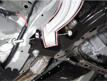
Loosen the bolt and nut of the compression arm on the subframe.
Tightening torque: 156.9 - 176 N·m
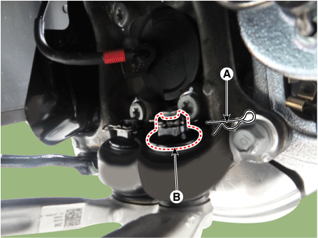
Loosen the compression arm pin (A) and nut (B).
Tightening torque: 88.3–108 N·m
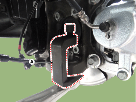
Disconnect the wheel speed sensor connector.
Remove the compression arm using a ball joint remover (A).
Install in the reverse order of removal.
Inspect the front wheel alignment.
(See Suspension System - Alignment)
[AWD Compression Arm]
Remove the wheel nuts, then remove the front wheel and tire (A) from the hub.
Tightening torque: 107.9–128 N·m
Remove the front wheel guard.
Remove the engine room side cover.
D 2.2 R VGT (See Engine Mechanical System - Under Engine Room Cover)
G 2.0 T-GDI THETA II (See Engine Mechanical System - Engine Room). Under Cover")
G 3.3 T-GDI LAMBDA II (See Engine Mechanical System - Engine Room). Under Cover")
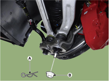
Loosen the compression arm pin (A) and nut (B).
Tightening torque: 88.3–108 N·m
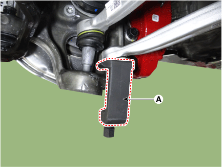
Remove the compression arm using a ball joint remover (A).
Loosen the bolt and nut of the compression arm on the subframe.
Tightening torque: 156.9 - 176 N·m
Install in the reverse order of removal.
Inspect the front wheel alignment.
(See Suspension System - Alignment)
Inspection
Inspect the lower arm bushings for damage or signs of aging. If necessary, replace the lower arm assembly.
Inspect the side arm for damage or deformation.
Inspect all bolts.
Test yourself
A quick Kia Stinger CK quiz: every answer comes with an explanation and a link to the manual page.