Subframe
Repair Procedures
Removal
[2WD]
Remove the wheel nuts, then remove the front wheel and tire (A) from the hub.
Tightening torque: 107.9–128 N·m

Loosen the nut and separate the stabilizer link from the front shock absorber.
Tightening torque: 98.1 - 118 N·m

Loosen the bolts (A) and remove the stabilizer bar.
Tightening torque: 49.0–64 N·m

Remove the engine room side cover.
D 2.2 R VGT (See Engine Mechanical System - Under Engine Room Cover)
G 2.0 T-GDI THETA II (See Engine Mechanical System - Engine Room). Under Cover")
G 3.3 T-GDI LAMBDA II (See Engine Mechanical System - Engine Room). Under Cover")
Disconnect the R-MDPS connector (A) and clip (B).

Loosen the shaft coupling bolt (A), then separate the shaft coupling.
Tightening torque: 32.4 – 37 N·m

Disconnect the R-MDPS wiring clip (A) from the subframe.

Remove the tie rod end nut.
Tightening torque: 88.3–108 N·m

Remove the steering knuckle using a ball joint remover (A).
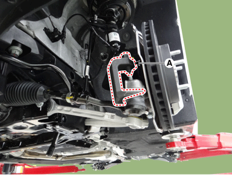
Loosen the gearbox bolts (A) and remove the gearbox.

Remove the front wheel guard.

Remove the side arm.
Tightening torque: 117.7–132 N·m

Loosen the bolt and nut of the compression arm on the subframe.
Tightening torque: 156.9–176 N·m

Remove the hood assembly.
(Refer to Body - Hood Assembly)
Assemble the engine mount in the engine compartment.
(Refer to Special Service Tools — "Engine Mount Assembly Drawing")

Disconnect the semi-active engine mount connector (A). [R 2.2]
[LH]
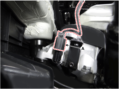
[RH]

Loosen the bolt of the intercooler intake hose. [R 2.2]
Tightening torque: 9.8–11.8 N·m

Loosen the engine mount insulator nut (A).
Tightening torque: 63.7–83 N·m
[RH]
[2.0 T-GDI THETA II, R 2.2]

[LH]

[3.3 T-GDI LAMBDA II]

Remove the clamp (A) from the subframe.
[3.3 T-GDI LAMBDA II]
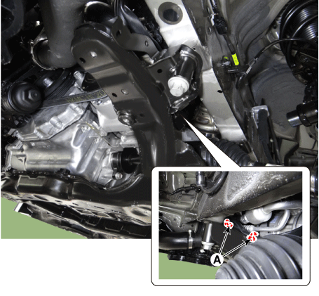
Loosen the bolts (A) and remove the subframe.
Tightening torque: 176.5–196 N·m

Remove the engine bracket from the subframe.
Tightening torque: 49.0–64 N·m

Install in the reverse order of removal.
Inspect the front wheel alignment.
(See Suspension System - Alignment)
[AWD]
Remove the wheel nuts, then remove the front wheel and tire (A) from the hub.
Tightening torque: 107.9–128 N·m
Remove the front wheel guard.
Remove the engine room side cover.
D 2.2 R VGT (See Engine Mechanical System - Under Engine Room Cover)
G 2.0 T-GDI THETA II (See Engine Mechanical System - Engine Room). Under Cover")
G 3.3 T-GDI LAMBDA II (See Engine Mechanical System - Engine Room). Under Cover")
Remove the side arm.
Tightening torque: 117.7–132 N·m
Loosen the bolt and nut of the compression arm on the subframe.
Tightening torque: 156.9–176 N·m
Loosen the nut and separate the stabilizer link from the front shock absorber.
Tightening torque: 98.1–118 N·m
Loosen the bolts (A) and remove the stabilizer bar.
Tightening torque: 49.0–64 N·m
Disconnect the R-MDPS connector (A) and clip (B).
Loosen the shaft coupling bolt (A), then separate the shaft coupling.
Tightening torque: 32.4 – 37 N·m
Disconnect the R-MDPS wiring clip (A) from the subframe.
Loosen the gearbox bolts (A) and remove the gearbox.
Remove the hood assembly.
(Refer to Body - Hood Assembly)
Assemble the engine mount in the engine compartment.
(Refer to Special Service Tools — "Engine Mount Assembly Drawing")
Disconnect the semi-active engine mount connector (A). [R 2.2]
[LH]
[RH]
Loosen the bolt of the intercooler intake hose. [R 2.2]
Tightening torque: 9.8–11.8 N·m
Loosen the engine mount insulator nut (A).
Tightening torque: 63.7–83 N·m
[RH]
[2.0 T-GDI THETA II, R 2.2]
[LH]
[3.3 T-GDI LAMBDA II]
Remove the clamp (A) from the subframe.
[3.3 T-GDI LAMBDA II]
Loosen the bolts (A) and remove the subframe.
Tightening torque: 176.5–196 N·m
Remove the engine bracket from the subframe.
Tightening torque: 49.0–64 N·m
Install in the reverse order of removal.
Inspect the front wheel alignment.
(See Suspension System - Alignment)
Test yourself
A quick Kia Stinger CK quiz: every answer comes with an explanation and a link to the manual page.