Piston and Connecting Rod
Repair Procedures
Disassembly
Remove the engine and transmission assembly.
(See Engine and Transaxle Assembly - Engine and Transaxle Installation)
Remove the automatic transmission.
(Refer to Automatic Transmission System - Automatic Transmission)
Remove the drive plate.
(Refer to Cylinder Block - Drive Plate)
Remove the front drive shaft. (If equipped with all-wheel drive)
(Refer to Drive Shaft and Axle — "Front Propeller Shaft")
Remove the front differential assembly. (If equipped with all-wheel drive)
(Refer to Drive Shaft and Axle - Front Differential Carrier)
Remove the rear oil seal.
(Refer to Cylinder Block - Rear Oil Seal)
Install the engine assembly on an engine stand for disassembly.
Remove the intake manifold.
(See Intake and Exhaust System - Intake Manifold)
Remove the exhaust manifold.
(Refer to Intake and Exhaust System - Turbocharger and Exhaust Manifold)
Remove the timing chain.
(See Timing System - Timing Chain)
Remove the air conditioning compressor.
(See Heating, Ventilation and Air Conditioning - Compressor)
Remove the generator.
(See Engine Electrical System - "Alternator")
Remove the water temperature control assembly.
(See Cooling System - "Water Temperature Control Assembly")
Remove the cylinder head assembly.
(See Cylinder Head Assembly - Cylinder Head)
Remove the balance shaft and oil pump.
(Refer to Lubrication System - Balance Shaft and Oil Pump)
Remove the ladder frame.
(Refer to Cylinder Block - Cylinder Block)
Check the connecting rod side clearance.
Remove the connecting rod caps and inspect the oil clearance.
Remove the piston and connecting rod assembly.
Using a ridge reamer, remove all carbon from the top of the cylinder.
Remove the connecting rod bearing cap (A).

Push the piston, connecting rod assembly and upper bearing out through the top of the cylinder block.
Check the fit between the piston and piston pin.
Try to move the piston back and forth on the piston pin. If any movement is felt, replace the piston and pin as a set.
Remove the piston rings.
Using a piston ring expander, remove the 2 compression rings (A).
Remove the oil control ring and expander spring (B) by hand.
Remove the connecting rod from the piston.
Remove the snap ring (C) from the piston.
Remove the piston pin (D) from the piston.
Disassemble the piston (F) and connecting rod (E).

Inspection
Connecting Rod
Check the connecting rod side clearance.
Using a feeler gauge, measure the connecting rod side clearance while moving the connecting rod back and forth.
Side clearance: Standard: 0.10–0.25 mm (0.0039–0.0098 in.)
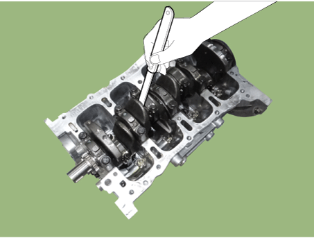
If out of specification, install a new connecting rod.
If still out of specification, replace the crankshaft.
Check the oil clearance of the connecting rod bearing.
Make sure the alignment marks on the connecting rod and cap are aligned to ensure correct assembly.
Remove the 2 connecting rod cap bolts.
Remove the connecting rod cap and bearing half.
Clean the connecting rod journal and bearing.
Place a piece of Plastigage across the connecting rod journal.

Install the bearing half and cap in place, then tighten the bolts.
Tightening torque: 17.7 – 22 N·m N·m + 88 – 92°
Remove the 2 bolts, the connecting rod cap and the bearing half.
Measure the Plastigage at its widest point.
Standard oil clearance: 0.033–0.051 mm (0.00130–0.00201 in.)

If the Plastigage is too wide or too narrow, remove the upper bearing half, install a new bearing assembly with the same color code (select the color as shown in the following column), and re-check the clearance.
If the Plastigage shows the clearance is still incorrect, try the next larger or smaller bearing (the color above or below the one specified) and recheck the clearance.
Connecting Rod Identification Mark

Connecting Rod Specifications
Grade Mark Inner Diameter a A 51.000 – 51.006 mm
(2.00787–2.00811 in.)D B 51.006 – 51.012 mm
(2.00811–2.00834 in.)c C 51.012 – 51.018 mm
(2.00834–2.00858 in.)
Crankshaft Pin Identification Mark

Crankshaft Specifications
Grade Mark Pin Outside Diameter I 1 47.966 – 47.972 mm
(1.88842–1.88866 in.)II 2 47.960 – 47.966 mm
(1.88819–1.88842 in.)III 3 47.954 – 47.960 mm
(1.88795–1.88819 in.)
Connecting Rod Bearing Identification Mark

Connecting Rod Bearing Specifications
Grade Mark Bearing Thickness AA Blue 1.515 – 1.518 mm
(0.0596–0.0598 in.)A Black 1.512 – 1.515 mm
(0.0595–0.0596 in.)B None 1.509 – 1.512 mm
(0.0594–0.0595 in.)C Green 1.506 – 1.509 mm
(0.0593–0.0594 in.)D Yellow 1.503 – 1.506 mm
(0.0592–0.0593 in.)
Connecting Rod Bearing Selection Table
Crankshaft Marking Connecting Rod Marking Bearing Classification Assembly I (1) A (A) D (yellow) B (B) C (green) C (C) B (none) II (2) A (A) C (green) B (B) B (none) C (C) A (black) III (3) A (A) B (none) B (B) A (black) C (C) AA (blue)
Inspect the connecting rods.
When reinstalling, make sure the cylinder numbers stamped on the connecting rod and cap match those marked during disassembly. When installing a new connecting rod, make sure the notches that hold the bearing in place are on the same side.
Replace the connecting rod if it is damaged on the thrust surfaces at either end. Also, if the small end inner diameter shows stepped wear or a heavily roughened surface, the connecting rod must also be replaced.
Using the connecting rod alignment tool, check the connecting rod for twist and bend.
Allowable connecting rod bend:
0.05 mm (0.0020 in.) or less per 100 mm (3.94 in.)
Allowable connecting rod twist:
0.10 mm (0.0039 in.) or less for 100 mm (3.94 in.)
Piston
Clean the piston
Using a gasket scraper, remove carbon deposits from the top of the piston.
Using a ring groove cleaning tool or a broken piston ring, clean the piston ring grooves.
Using solvent and a brush, thoroughly clean the piston.
Check the piston-to-cylinder clearance by calculating the difference between the cylinder bore diameter and the piston outer diameter.
Piston-to-cylinder clearance: 0.020–0.040 mm (0.00079–0.00157 in.)
Using a cylinder bore gauge, measure the cylinder bore diameter in the thrust and axial directions.
Standard diameter: 86.00–86.03 mm (3.3858–3.3870 in.)

Measure the standard piston outside diameter at 17 mm (0.67 in.) from the top surface of the piston.
Standard diameter: 85.970–86.000 mm (3.38465–3.38583 in.)

Select a piston that matches the cylinder bore size class.
Check the cylinder bore size code on the cylinder block surface.

Cylinder bore inside diameter
Size code Cylinder Inner Diameter A 86.00 - 86.01 mm
(3.3858–3.3862 in.)B 86.01 - 86.02 mm
(3.3862–3.3866 in.)C 86.02 - 86.03 mm
(3.3866–3.3870 in.)Check the piston size mark on the piston top surface.
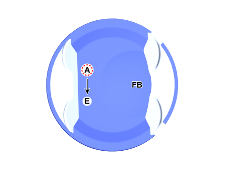
Piston outside diameter
Size code Piston Outer Diameter A 85.970 - 85.980 mm
(3.38465 - 3.38504 in.)B 85.980 - 85.990 mm
(3.38504 - 3.38543 in.)C 85.990 - 86.000 mm
(3.38543 - 3.38583 in.)
Piston Rings
Inspect the piston ring side clearance.
Using a feeler gauge, measure the clearance between a new piston ring and the ring groove wall.
Piston Ring Side Clearance
Standard
No. 1: 0.050–0.080 mm (0.00197–0.00315 in.)
No. 2: 0.040–0.080 mm (0.00157–0.00315 in.)
Oil ring: 0.020–0.055 mm (0.00079–0.00217 in.)

If the clearance is greater than the maximum, replace the piston.
Inspect the piston ring end gap.
To measure the piston ring end gap, insert the piston ring into the cylinder bore. Position the ring at a right angle to the cylinder wall by pushing it slightly with the piston. Measure the gap with a feeler gauge. If the gap exceeds the service limit, replace the piston ring. If the gap is still too large, check the cylinder bore diameter against the wear limit. If the bore exceeds the service limit, replace the cylinder block.
Piston Ring End Gap
Standard
No. 1: 0.15–0.25 mm (0.0059–0.0098 in.)
No. 2: 0.25–0.40 mm (0.0098–0.0157 in.)
Oil ring: 0.20–0.40 mm (0.0079–0.0157 in.)

Piston Pin
Measure the piston pin diameter.
Piston pin diameter: 21.997–22.000 mm (0.86602–0.86614 in.)

Measure the piston pin-to-piston clearance.
Piston pin-to-piston clearance: 0.003–0.012 mm (0.00012–0.00047 in.)
Check the oil clearance between the piston pin and the connecting rod bushing.
Piston pin-to-connecting rod clearance: 0.005–0.016 mm (0.00020–0.00063 in.)
Installation
Assemble the piston and connecting rod.
Piston pin outside diameter:
21.995–22.000 mm (0.86594–0.86614 in.)
Piston pin hole inside diameter:
22.003–22.007 mm (0.86626–0.86642 in)
Connecting rod small end inside diameter:
22.005–22.011 mm (0.86634–0.86657 in)
Interference:
-0.014 to -0.005 mm (-0.0006 to -0.0002 in.)
Install the snap ring (A) on one side of the piston pin hole.
Align the piston front mark with the connecting rod front mark.

Insert the piston pin (B) into the piston pin hole and the connecting rod small end hole.
Assembly temperature
Piston: 70–80 °C
Connecting rod and piston pin: Room temperature
Install the snap ring (C) on the other side after inserting the piston pin.

Install the piston rings.
Install the oil control ring with the coil spring by hand.
Using a piston ring expander, install the 2 compression rings with the code mark facing up.
Position the piston rings so that the ring end gaps are as shown in the illustration.

Install the connecting rod bearings.
Align the bearing tab with the groove in the connecting rod or connecting rod cap.
Install the bearings (A) in the connecting rod and connecting rod cap (B).

Install the piston and connecting rod assembly.
Install the ring compressor, check that the bearings are seated correctly, then insert the piston into the cylinder and tap it in with the wooden handle of a hammer.

Stop after the ring compressor is released and check the alignment of the connecting rod and crankpin before fully inserting the piston.
Apply engine oil to the bolt threads. Install the connecting rod caps (A) with the bearings and tighten the bolts.
Tightening torque: 17.7 – 22 N·m N·m + 88 – 92°
Check the connecting rod side clearance.
Assemble the remaining components in the reverse order of removal.
Test yourself
A quick Kia Stinger CK quiz: every answer comes with an explanation and a link to the manual page.