Smart Cruise Control (Stop & Go) (SCC) Unit-Radar
Specifications
Specification
| Item | Specification |
| Power Supply (V) | 12 |
| Operating Voltage (V) | 9 - 16 |
Description and Operation
Description
The Smart Cruise Control unit is installed at the front right side of the chassis. The radar sensor is built into the front of the unit. This sensor detects vehicles and objects ahead of the vehicle. The radar sensor can detect up to 64 objects ahead of the vehicle. A warning is triggered when the vehicle deviates from the reference points of horizontal and vertical alignment during operation. This sensor communicates with the instrument cluster, warning buzzer, smart cruise control switch, Electronic Stability Program (ESP), ECM and TCM via the CAN bus. The sensor monitors vehicle speed through CAN communication between the ESP system and the ECM and TCM.
Circuit Diagrams
Schematic Diagrams
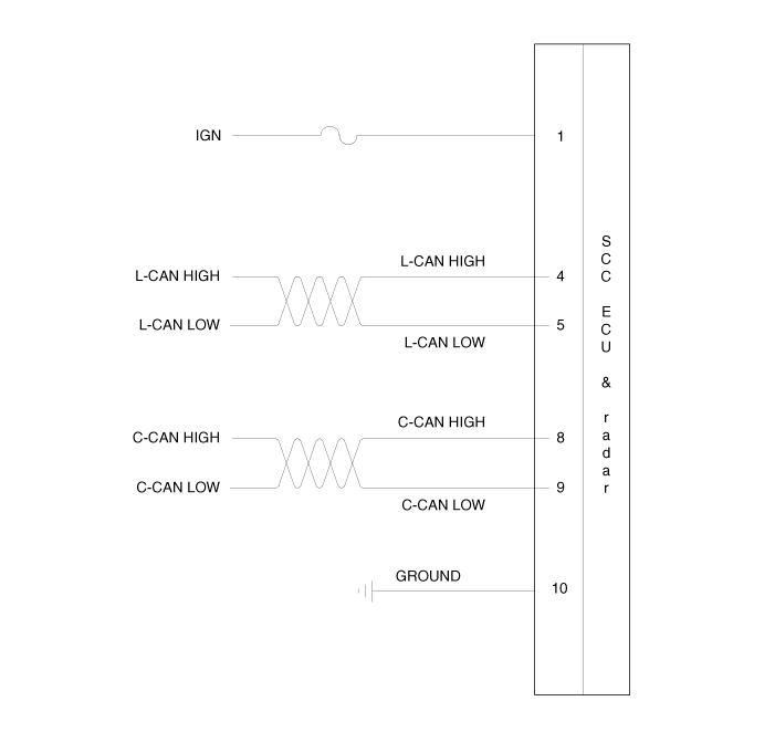
Terminal Function
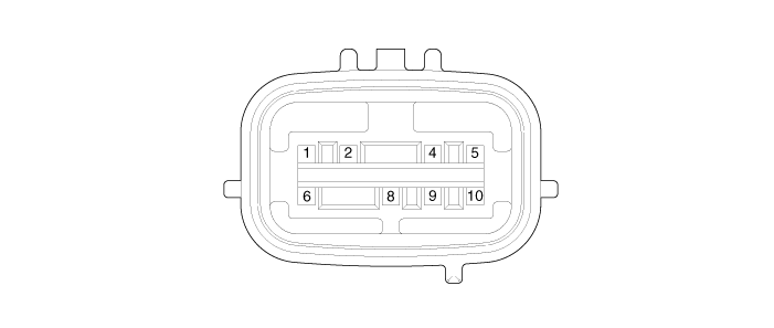
| Pin No. | Terminal Function |
| 1 | IGN |
| 2 | - |
| 3 | - |
| 4 | L-CAN HIGH |
| 5 | L-CAN LOW |
| 6 | - |
| 7 | - |
| 8 | C-CAN HIGH |
| 9 | C-CAN LOW |
| 10 | GROUND |
Repair Procedures
Inspection
Inspection procedures for front radar system malfunction:
Inspect the front bumper appearance and accident history (bumper appearance, vehicle service history, and bumper replacement history).
→ If the vehicle has been involved in an accident, the front radar unit mounting is likely to be twisted.
Check whether the radar cover on the bumper is contaminated.
After starting the engine, check the warning message on the cluster and the DTC.
Removal
Turn the ignition switch OFF and disconnect the negative (-) battery cable.
Remove the front bumper assembly.
(Refer to Body - "Front Bumper Assembly")
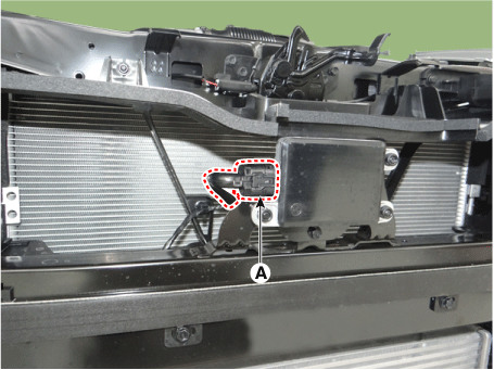
Disconnect the front radar connector (A).
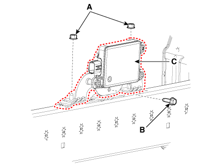
Loosen the nuts (A) and bolt (B), then remove the front radar (C).
Tightening torque: (A, B): 9.8–11.8 N·m
Installation
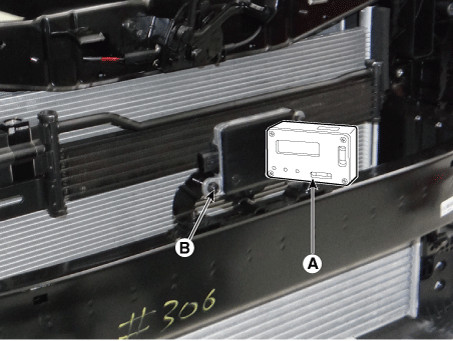
Check the last 2 digits of the lot number. Before installing the front radar, check the label (A) on the back.

Install the front radar (A), tightening the nuts.
Tightening Torque: 9.8–11.8 N·m
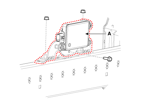
Connect the front radar connector (A).
If the front radar has been replaced with a new one, perform the variant coding procedure using KDS.

Check and adjust the front radar alignment angle.
Perform the "front radar mounting angle inspection/adjustment" using KDS.
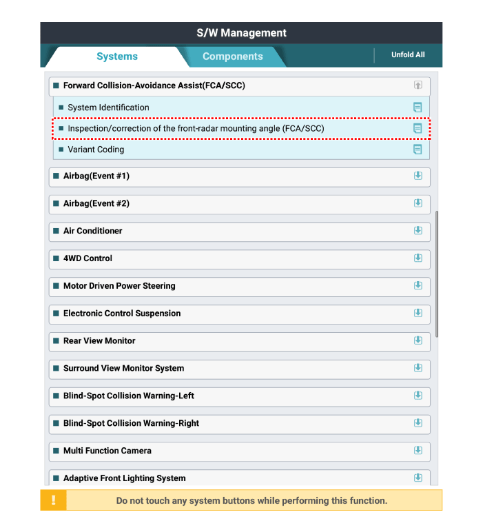
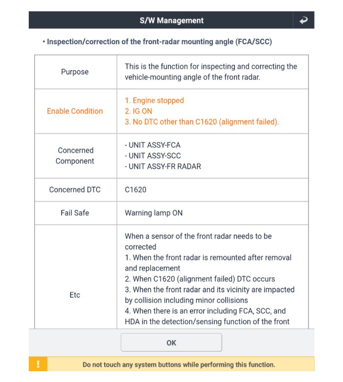
Enter the 2-digit value in the code input field, then click "OK".

Check the vertical angle compensating for error using KDS.

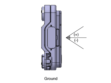
Check the front radar vertical angle using a vertical protractor (inclinometer).
Adjust the "target vertical angle" by turning the adjusting screw (B) of the front radar.
Clockwise rotation: adjusts the angle (+)
Counterclockwise rotation: adjusts the angle (-)
Number of turns of the adjusting screw Correction angle Clockwise Counterclockwise 0,5 + 0,5° - 0,5° 1 + 1,0° - 1,0° 1,5 + 1,5° - 1,5° 2 + 2,0° - 2,0° 2,5 + 2,5° - 2,5° 3 + 3,0° - 3,0° 3,5 + 3,5° - 3,5° 4 + 4,0° - 4,0° 4,5 + 4,5° - 4,5° 5 + 5,0° - 5,0°
Install the front bumper assembly.
(Refer to Body - "Front Bumper Assembly")
Perform the front radar verification/adjustment procedure using the TCT.
(Refer to Engine Electrical System – "Smart Cruise Control (Stop & Go) Unit-Radar")
Adjustment
Front Radar Mounting Angle Inspection/Adjustment Overview
The front radar detects objects in front of the vehicle and recognizes the distance to the object, relative speed, etc. For these reasons, the installation direction must be linear with the vehicle. Therefore, angle inspection and adjustment must be performed when the front radar is repaired due to an accident or malfunction, or when a new front radar is replaced.
The accuracy of the front radar cannot be guaranteed if inspection and adjustment have not been performed properly.
Front radar inspection/adjustment must be performed in any of the stop modes (C1) using the KDS.
Perform the adjustment procedure with the exclusive adjustment reflector (SST) for the stop mode (C1).
How to inspect/adjust the front radar mounting angle – Stop Mode
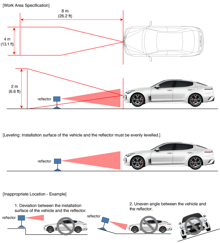
Park the vehicle on a level surface.
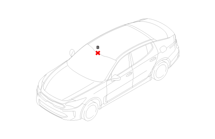
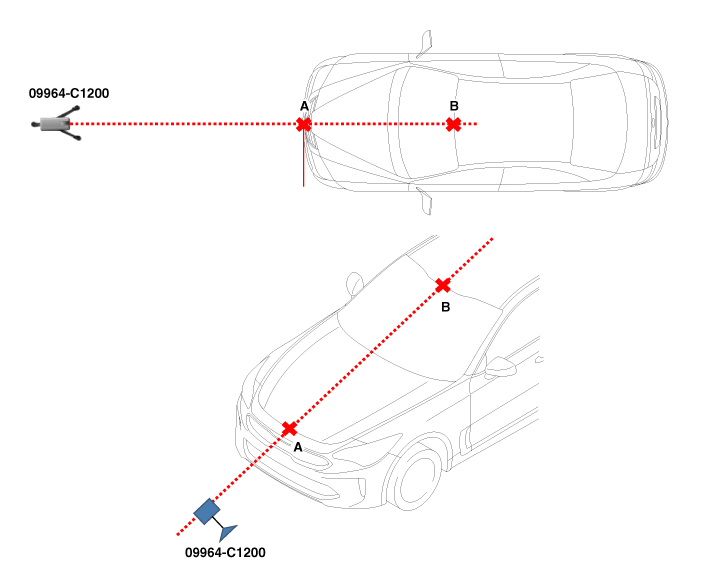
Mark the center point of the emblem (A).

Mark the center point (B) after measuring the distance from the top of the windshield.
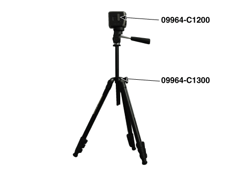
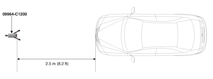
Install the laser (09964-C1200) on the tripod (09964-C1300).
Place the laser (09964-C1200) 2.5 m (8.2 ft) from the front of the vehicle.
Align the vertical laser line with (A) and (B) using the laser (09964-C1200).
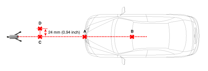
Mark (C) at a distance of 2.5 m (8.2 ft) from (A) in front of the vehicle.

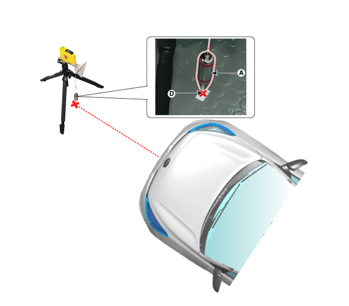
Mark (D) at a point 24 mm (0.94 in.) from (C) to the left in the vertical direction.
Remove the laser (09964-C1200) from the tripod (09964-C1300).
Install the reflector (09964-C1100) on the tripod (09964-C1300).

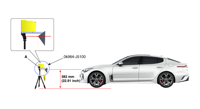
Install the reflector adapter (0K964-J5100) on the reflector (09964-C1100).
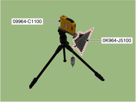
Set the reflector to a horizontal position using the leveler (A) built into the tripod (09964-C1300).
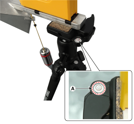
Align the vertical weight (A) of the reflector (09964-C1100) with point (D).
Set the height of the reflector adapter (0K964-J5100) to 582 mm (22.91 in.).
Remove the vertical weight from the reflector (09964-C1100).
Inspect the front radar and the front bumper surface again for the following: objects with eyes.
Select C1 (Stop mode) to check and adjust the front radar alignment angle by following the procedure on the KDS screen.
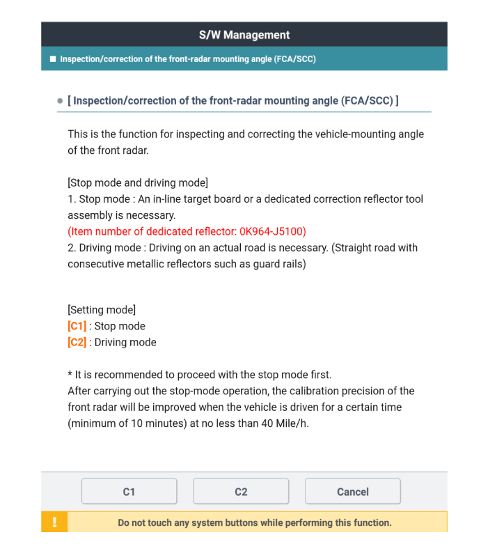
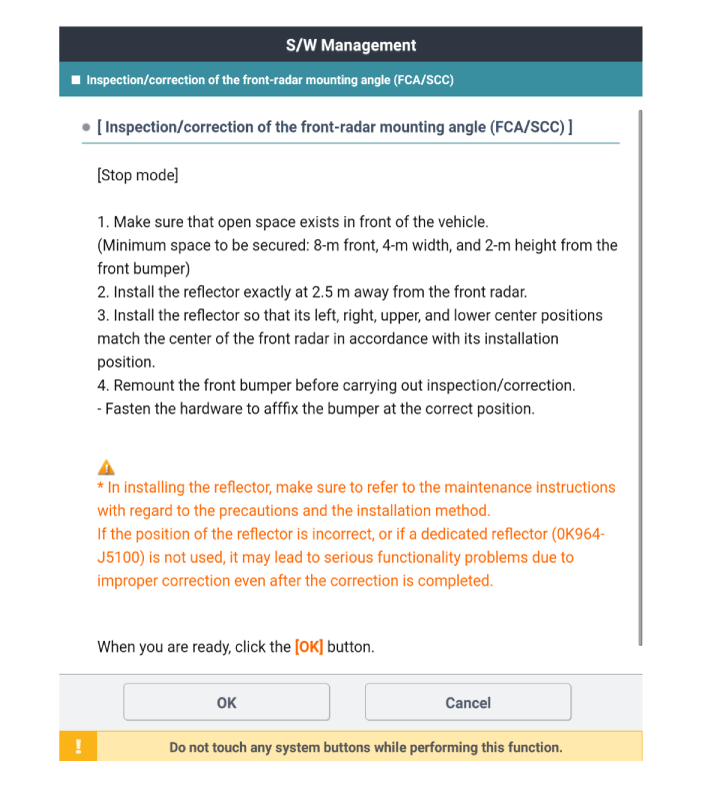

If the front radar inspection/adjustment fails, check the inspection/adjustment conditions.
Test yourself
A quick Kia Stinger CK quiz: every answer comes with an explanation and a link to the manual page.