window regulator switch
Components and Components Location
COMPONENTS LOCATION
DRIVER WINDOW SWITCH
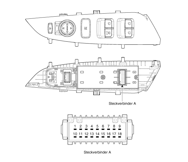
CONNECTOR PIN ASSIGNMENT
[Driver Side Front/Rear Window Protection - Auto Close/Open]
(LHD)
| No. | Description | No. | Description |
| 1 | Front Right Window Regulator (Close) | 10 | Rear Right Window Regulator (Close) |
| 2 | - | 11 | Rear Right Power Window "Down" |
| 3 | Front Right Window Regulator (Open) | 12 | Battery (+)_RH |
| 4 | - | 13 | Tail lamp |
| 5 | Left Window Lock Switch | 14 | Right Window Lock Switch |
| 6 | Driver Side Window Regulator Main Module (Close/Open) | 15 | Rear Left Power Window "Up" |
| 7 | - | 16 | Rear Left Power Window "Down" |
| 8th | Dimensions | 17 | - |
| 9 | - | 18 | Battery (+)_LH |
(RHD)
| No. | Description | No. | Description |
| 1 | - | 10 | Rear Right Window Regulator (Close) |
| 2 | - | 11 | Rear Right Power Window "Down" |
| 3 | - | 12 | Battery (+)_RH |
| 4 | - | 13 | Tail lamp |
| 5 | Left Window Lock Switch | 14 | Right Window Lock Switch |
| 6 | Driver Side Window Regulator Main Module (Close/Open) | 15 | Rear Left Power Window "Up" |
| 7 | Front Left Window Regulator (Close) | 16 | Rear Left Power Window "Down" |
| 8th | Dimensions | 17 | - |
| 9 | Front Left Window Regulator (Open) | 18 | Battery (+)_LH |
[Driver Side Front Window Protection - Auto Close/Open]
(LHD)
| No. | Description | No. | Description |
| 1 | Front Right Window Regulator (Close) | 10 | - |
| 2 | - | 11 | - |
| 3 | Front Right Window Regulator (Open) | 12 | Battery (+)_RH |
| 4 | - | 13 | Tail lamp |
| 5 | - | 14 | - |
| 6 | Driver Side Window Regulator Main Module (Close/Open) | 15 | - |
| 7 | - | 16 | - |
| 8th | Dimensions | 17 | - |
| 9 | - | 18 | - |
(RHD)
| No. | Description | No. | Description |
| 1 | - | 10 | - |
| 2 | - | 11 | - |
| 3 | - | 12 | - |
| 4 | - | 13 | Tail lamp |
| 5 | - | 14 | - |
| 6 | Driver Side Window Regulator Main Module (Close/Open) | 15 | - |
| 7 | Front Left Window Regulator (Close) | 16 | - |
| 8th | Dimensions | 17 | - |
| 9 | Front Left Window Regulator (Open) | 18 | Battery (+)_LH |
[Auto Open Front / Rear]
(LHD)
| No. | Description | No. | Description |
| 1 | Front Right Window Regulator (Close) | 10 | Rear Right Window Regulator (Close) |
| 2 | - | 11 | Rear Right Power Window "Down" |
| 3 | Front Right Window Regulator (Open) | 12 | Battery (+)_RH |
| 4 | - | 13 | Tail lamp |
| 5 | Left Window Lock Switch | 14 | Right Window Lock Switch |
| 6 | - | 15 | Rear Left Power Window "Up" |
| 7 | Front Left Window Regulator (Close) | 16 | Rear Left Power Window "Down" |
| 8th | Dimensions | 17 | - |
| 9 | Front Left Window Regulator (Open) | 18 | Battery (+)_LH |
(RHD)
| No. | Description | No. | Description |
| 1 | Front Right Window Regulator (Close) | 10 | Rear Right Window Regulator (Close) |
| 2 | - | 11 | Rear Right Power Window "Down" |
| 3 | Front Right Window Regulator (Open) | 12 | Battery (+)_RH |
| 4 | - | 13 | Tail lamp |
| 5 | Left Window Lock Switch | 14 | Right Window Lock Switch |
| 6 | - | 15 | Rear Left Power Window "Up" |
| 7 | Front Left Window Regulator (Close) | 16 | Rear Left Power Window "Down" |
| 8th | Dimensions | 17 | - |
| 9 | Front Left Window Regulator (Open) | 18 | Battery (+)_LH |
[Auto Open Front]
(LHD)
| No. | Description | No. | Description |
| 1 | Front Right Window Regulator (Close) | 10 | - |
| 2 | - | 11 | - |
| 3 | Front Right Window Regulator (Open) | 12 | Battery (+)_RH |
| 4 | - | 13 | Tail lamp |
| 5 | - | 14 | - |
| 6 | - | 15 | - |
| 7 | Front Left Window Regulator (Close) | 16 | - |
| 8th | Dimensions | 17 | - |
| 9 | Front Left Window Regulator (Open) | 18 | Battery (+)_LH |
(RHD)
| No. | Description | No. | Description |
| 1 | Front Right Window Regulator (Close) | 10 | - |
| 2 | - | 11 | - |
| 3 | Front Right Window Regulator (Open) | 12 | Battery (+)_RH |
| 4 | - | 13 | Tail lamp |
| 5 | - | 14 | - |
| 6 | - | 15 | - |
| 7 | Front Left Window Regulator (Close) | 16 | - |
| 8th | Dimensions | 17 | - |
| 9 | Front Left Window Regulator (Open) | 18 | Battery (+)_LH |
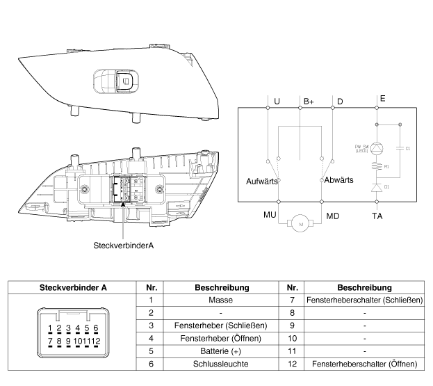
PASSENGER WINDOW SWITCH
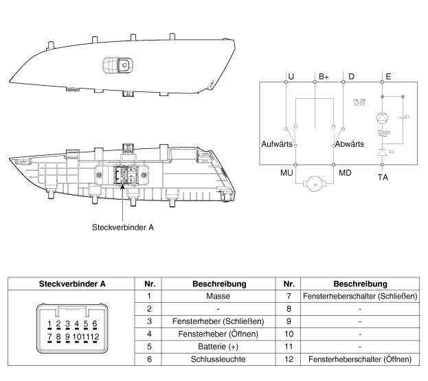
Rear Window Switch
repair procedures
expansion
DRIVER WINDOW SWITCH
Disconnect the battery ground cable.
Remove the driver side front door panel.
(See Body - Front Door Panel)
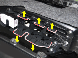
Pull both ends of the switch holders to remove the power window switch (A). (B) Remove.
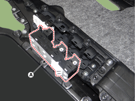
PASSENGER WINDOW SWITCH
Disconnect the battery ground cable.
Remove the front right door panel.
(See Body - Front Door Panel)
Loosen the mounting screws and remove the power window switch (A).
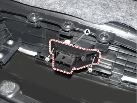
Rear Window Switch
Disconnect the battery ground cable.
Remove the rear door panel.
(See Body - Rear Door Panel)
Loosen the mounting screws and remove the power window switch (A).
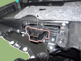
Installation
DRIVER WINDOW SWITCH
Install the driver side power window switch.
Connect the connectors and install the front door panel.
Connect the negative (-) battery terminal.
PASSENGER WINDOW SWITCH
Install the passenger side window regulator switch.
Connect the connectors and install the front door panel.
Connect the negative (-) battery terminal.
Rear Window Switch
Install the rear window switch.
Connect the connectors and install the rear door panel.
Connect the negative (-) battery terminal.
TEST
DRIVER WINDOW SWITCH
Disconnect the battery ground cable.
Remove the driver side front door panel.
Disconnect the window regulator switch connector from the door panel.
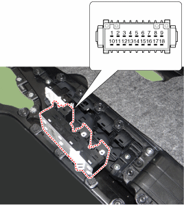
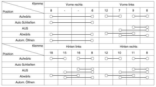
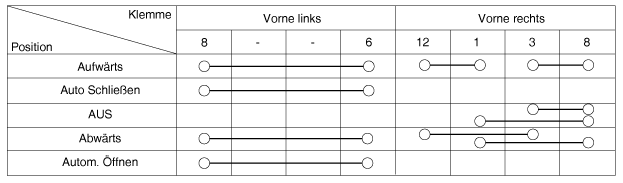
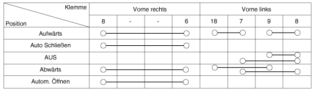
In the switch positions shown in the following table, check continuity between the terminals. If continuity is not as specified, replace the switch.
[Driver Front/Rear Window Protection - Auto Close/Open]
(LHD)
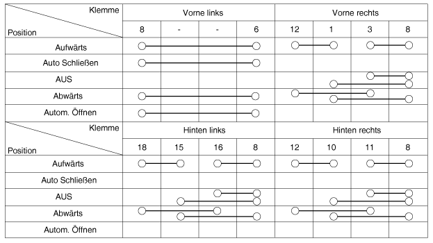
(RHD)
[Front Driver Window Regulator Protection - Auto Close/Open]
(LHD)
(RHD)
[Auto Open Front Rear]
(LHD)
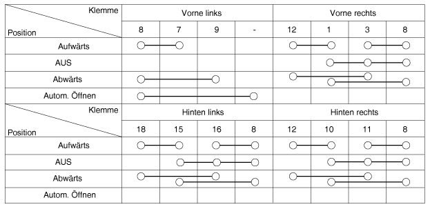
(RHD)
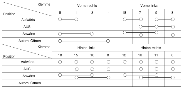
[Auto Open Front]
(LHD)
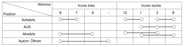
(RHD)
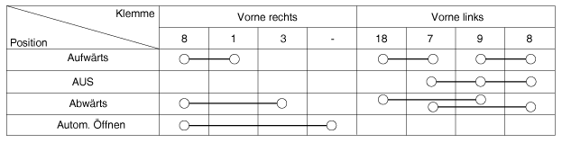
passenger/rear window regulator switch
Disconnect the battery ground cable.
Remove the front right door panel.
(See Body - Front Door Panel)
(See Body - Rear Door Panel)
Disconnect the window regulator switch connector from the door panel.
[passenger window switch]
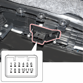
[Power Rear Window Switch]
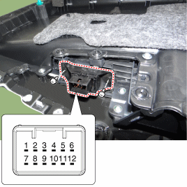
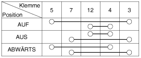
In the switch positions shown in the following table, check continuity between the terminals. If continuity is not as specified, replace the switch.
Diagnosis Using KDS
Faulty body electrical components can be quickly identified using the vehicle diagnostic system (KDS).
The diagnostic system (KDS) provides the following data.
Self-Diagnosis: Check and Display Diagnostic Trouble Code (DTC)
Current data: check the status of system inputs/outputs.
Actuator Test: Check the operating condition of the system.
Special Function: Control functions other than system options and zero setting
Select "Vehicle Model" and the system to be checked to select the vehicle. Check with the tester.
Select "Body Control Module (BCM)" to view the cluster module. Check the BCM.
Select the "Current Data" menu to view the current status of the input/output data. Search.
Input/output data of the sensors corresponds to the door lock switch being checked.
If the power door lock function is checked forcibly, the BCM actuator test must be selected.
Test yourself
A quick Kia Stonic quiz: every answer comes with an explanation and a link to the manual page.