In this manual: Electrochromic Interior Rear View Mirror
13steps
~83min
4/5difficulty
1special tools
Done 0 of 13
Bauteile und bauteile-Übersicht
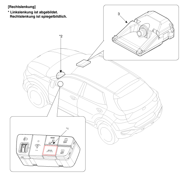
BAUTEILE-ÜBERSICHT
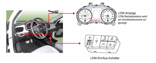
1. LDW ON/OFF Switch 2. Combination Meter
3. LDW-Einheit (MFC)
* MFC: Combination Camera
Function: LDW, HBA, FCA
Beschreibung und bedienung
Beschreibung
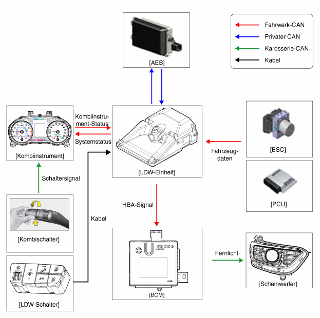
SYSTEM BLOCK DIAGRAM
LDW-Bauteile
OFF
No.
FUNCTION
LOCATION
1
LDW-Einheit
Spurhaltewarnung (LDW): Erfasst die aktuell vorausliegende Fahrspur und aktiviert die Warnfunktion, wenn das Fahrzeug droht, die aktuelle Fahrspur zu verlassen.
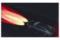
Fernlichtassistent (HBA): Erfasst die Scheinwerfer von entgegenkommenden Fahrzeugen und das Schlusslicht von vorausfahrenden Fahrzeugen und schaltet das Fernlicht EIN/AUS.
Windschutzscheibe
2
LDW Switch
LDW ON/OFF Switch
Instrument Panel (References)
3
Multi-function Switch
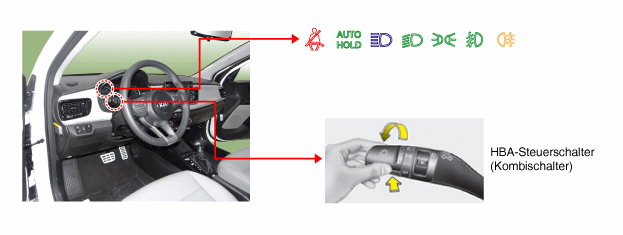
Ein-/Aus-Schalter HBA (MF: Auto-Modus
Steering Wheel
4
Combination Meter / Warning Chime
LDW Warning
COMBINATION METER
The LDW camera unit performs the following functions by processing the video input signal.
Erfasst und analysiert die aktuelle Fahrspur
Erfasst das Licht von vorausfahrenden und entgegenkommenden Fahrzeugen
Detects and analyzes the status of preceding and oncoming vehicles and generates a warning chime (or message) for the driver when necessary.
Übertragung der Informationen über die Hochgeschwindigkeits-CAN-Kommunikation
Spurhaltewarneinheit (LDW)
Spurhaltewarnung (LDW)
Fernlichtassistent (HBA)
Forward Collision-Avoidance Assist (FCA)
Spurhaltewarnung
Wenn Licht vom vorausfahrenden Fahrzeug erfasst wird
Erkennung von Fahrzeugen und Fußgängern
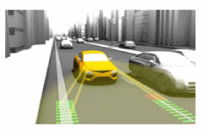
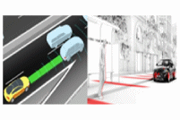
The Lane Departure Warning system is a convenience function that uses the camera image and vehicle signal data to detect the lanes ahead and warn the driver when the vehicle deviates from the lane. It uses a camera unit that detects the lane by analyzing the camera image input signal.
The sensor module, which processes the images of the lanes ahead captured by the camera unit, detects the lanes and analyzes the key lane-keeping parameters: vehicle deviation from lane center, road curvature, vehicle heading angle and curves. The following procedure is used to detect the lane using image processing.
Erfassung der Landschaft mithilfe des eingehenden Straßenbilds
Filterung und Berechnung durch Vergrößerung der Fahrspur
Extract lane candidate points.
(Die einzelnen Punkte werden als Fahrspur Interpretiert.)
Erfassung der Landschaft mithilfe der Kandidatenpunkte
LDW-Funktionssablauf
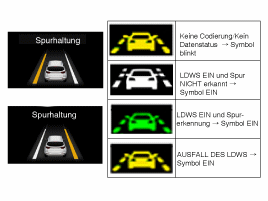
When the LDW switch is pressed, the operating status of the Lane Departure Warning system is shown in the center of the combination meter while the LDW indicator is illuminated.
Weitere Informationen zur Anzeige werden in der folgenden Tabelle aufgelistet.
Category
OPERATION
LDW Warning and Alarm
Control (Button)
On
LDW ON
OFF
LDW OFF
Betriebsstatus
Kombiinstrument-Kontrollleuchte
Betriebsbedingung
Activated when the vehicle speed exceeds the preset speed with LDW on.
[Start: 60 km/h ↑] [Stop: 55 km/h ↓]
※ The lane departure warning is not activated when the turn signal or hazard warning lights are on.
Fernlichtastant
Category
OPERATION
LDW Warning and Alarm
Control (Button)
On
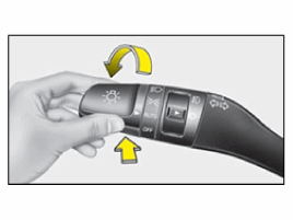
When the high beam switch is turned on (pressed/released) while the combination switch is set to AUTO.
HBA ON + Low Beam HBA ON + High Beam
OFF
Wenn der Fernlichtschalter wieder aktiviert wird, während der Kombischalter NICHT auf Auto steht oder wenn die HBA-Funktion eingeschaltet ist.
Betriebsstatus
Kombiinstrumentanzeige
Betriebsbedingung
Activated when the vehicle speed exceeds the preset speed with HBA on.
[Start: 45 km/h ↑] [Stop: 35 km/h ↓]
※ Activation occurs only when the combination switch is set to AUTO and the low beam is on.
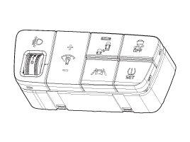
LDW ON/OFF Switch (A)
When the LDW switch is pressed, LDW is activated while the LDW indicator is illuminated. When the switch is pressed again, LDW is turned off and the indicator goes out.
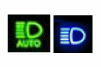
Automatic High Beam: The automatic high beam control system is activated when the combination switch is set to AUTO and the light switch is set to the high beam position (by pressing).
When the light switch is not set to AUTO or high beam, the automatic high beam control system is turned off.
LDW Warning Chime
Visueller Alarm: Die Spurlinie auf der Seite, in deren Richtung die Spur verlassen wird, blinkt "bernsteinfarben".
LDW-Betriebsbedingungen
Die Einschaltbedingungen des LDW sind wie folgt.
The LDW switch is turned ON. When the switch is on, the LDW indicator in the combination meter illuminates.
Die LDW-Funktion wird gesetzt und die Fahrzeuggeschwindigkeit überschreitet 60 km/h.
The alarm stops temporarily when the vehicle speed drops to 60 - 55 km/h, and restarts when the vehicle speed exceeds 60 km/h.
When the driver operates the left or right turn signal to indicate a lane change, no warning is issued regardless of the direction of the lane change.
The lane departure warning function restarts 2 seconds after the left or right turn signal is switched off. The warning is not output when the hazard warning flasher is operated.
Turn on the turn signal before changing lanes. If you change lanes without operating the turn signal in the direction of the lane change, a warning will be activated.
If more than 40% of the vehicle body leaves the lane, the warning is canceled and a lane change is assumed.
No lane departure warning is issued if the vehicle is driving in the center of the lane.
Repair Procedures
Autokalibrierung des Kameraziels (SPTAC)
Dieses Verfahren dient zur Kalibrieung der Kamera durch einen Mechaniker, der das Fahrzeug andhand einer gut beleuchteten Fahrspursimulation, die vorzugsweise an der Wand montiert ist, ausrichtet.
Für die LDW-Kamera wird ein Fehlercode "System nicht kalibriert" gesetzt, wenn die vorgeschriebenen Toleranzwerte nicht eingehalten werden.
Das LDW wird zum Austausch vor Ort mit dem Fehlercode "Systemkalibrierung erforderlich / Variantencodierungsfehler" ausgeliefert, wenn es sich um ein Ersatzteil handelt, das direkt vom Hersteller geliefert wird.
Richtlinien zur Auswahl eines geeigneten Ziels
Damit die LDW-Kalibrierung erfolgreich durchgeführt werden kann, müssen folgende Bedingungen erfüllt sein :
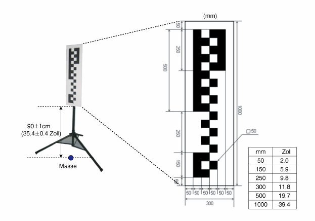
The target surface (SST: 09890-3V100) must face the camera squarely, horizontally and vertically, to allow a roll of max. 1°.
Das Ziel muss auf einem festen Hintergrundmaterial montiert sein, um die Flachheitsanforderungen zu erfüllen.
Das Ziel muss reflektierende (nicht verblasst oder schlecht gemalt) Fahrspurmarkierungen aufweisen.
The target size is 30 cm wide and 100 cm high.
Der Montagebereich darf KEINE schraffierten oder texturierten Fläche in der Nähe des Ziels aufweisen.
The target must be well illuminated with non-flickering light. No shadows may fall on the target.
Autokalibrierung des Kameraziels
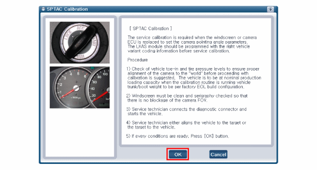
It is recommended to check the front wheel alignment and tire pressure before performing calibration, to ensure correct alignment of the camera to the "world". The vehicle must be loaded with the nominal production load during calibration.
The windshield must be clean and inspected so that the camera is not blocked.
The mechanic connects the diagnostic connector and starts the vehicle. The camera module must not be activated by pressing the switch.
Die Servicekalibrierung läuft möglicherweise nicht korrekt ab, wenn ein Systemfehler aktiv ist.
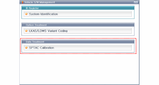
When working with a replacement ECU, the mechanic starts the SPTAC reset configuration.
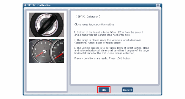
Der Mechaniker richtet entweder das Fahrzeug auf das Ziel oder das Ziel auf das Fahrzeug aus.
a.
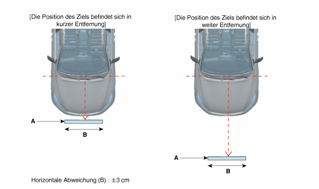
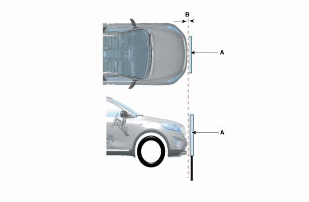
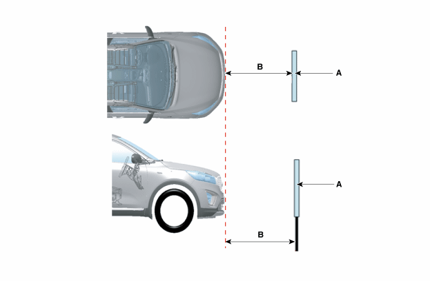
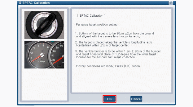
Die Unterseite des Ziels muss 90 ±1cm vom Boden entfernt und auf die Horizontalachse der Kamera ausgerichtet sein.
b.
The target position (A) for short distance is 0 ± 5 cm (B) in front of the front bumper.
b.
The target position (A) for long distance is 100 ± 5 cm (B) in front of the front bumper.
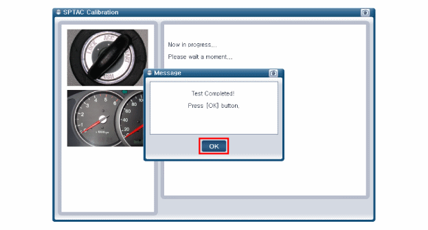
Nachdem die Position der Kalibrierungsvorrichtung für nahe Distanz überprüft wurde, am Diagnosegerät "OK" anklicken.
The mechanic ensures the correct position and checks for the "OK" message on the diagnostic tool (KDS).
Nachdem die Position der Kalibrierungsvorrichtung für weite Distanz überprüft wurde, am Diagnosegerät "OK" anklicken.
(Positionskalibrierung 2 Mal durchführen.)
The mechanic ensures the correct position and checks for the "OK" message on the diagnostic tool (KDS).
Alle Fehlercodes löschen.
Zündung aus- und dann wieder einschalten.
Test drive
?
Test yourself
A quick Kia Stonic quiz: every answer comes with an explanation and a link to the manual page.