Rear Parking Distance Warning Sensor (PDW-R)
Technical Data
SPECIFICATIONS
| No. | SPECIFICATIONS | |
| Ultrasonic sensor | Nennspannung (Rated Voltage) | Gleichstrom 12 V |
| Erkennungsbereich | (30 - 120 cm) | |
| Betriebstemperatur | Equal voltage 9 ~ 16 V | |
| Operating voltage | MAX. 350 mA | |
| Betriebstemperatur | -30 - 80 °C | |
| Arbeitsfrequenz | 48 ± 5 kHz | |
| Anzahl der Sensoren | 4 pins | |
Bauteile und bauteile-Übersicht
BAUTEILE-ÜBERSICHT
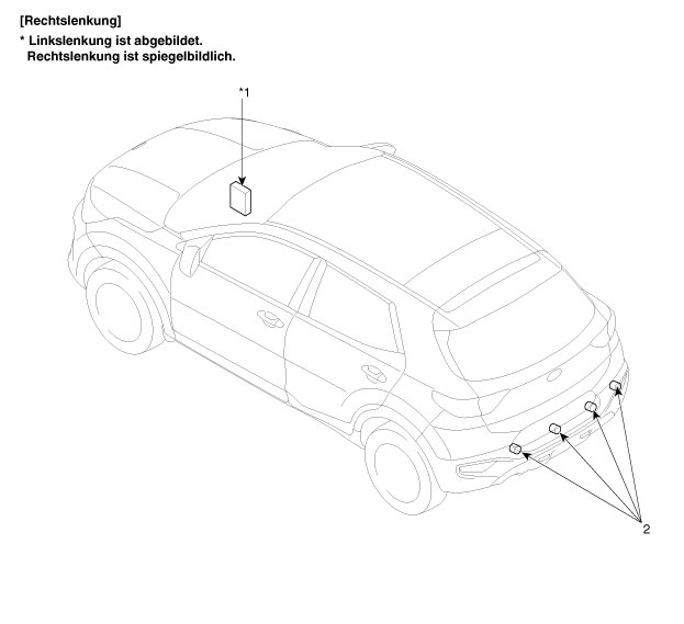
| 1. Karosserie-Steuermodul (BCM) | 2. Sensor for parking distance warning |
Beschreibung und bedienung
SYSTEM
Das PDW-R (System für Hintere Einpark-Abstandswarnung) ist eine elektronische Fahrhilfe, die beim Einparken bzw. Beim Fahren mit niedriger Geschwindigkeit Warnungen für den Fahrer ausgibt. Der Sensor verwendet Ultraschallwellen um Objekte in der Nähe des Fahrzeugs zu erfassen.
The PDW-R system consists of PDW-R sensors that detect obstacles and transmit the result, divided into three warning levels (1st/2nd/3rd), via the LIN communication line to the BCM. The BCM determines the warning level based on the messages transmitted from the slave sensors and activates the audible signal or transmits the data to the display.
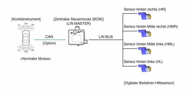
System operation specification
INIT-Modus
System initialization 500 ms after IGN1 ON and shift into reverse gear
PDW-R erkennt LID und setzt die Sensor-ID während der Initialisierung.
BCM initialization activates the PDW-R individual sensors and performs the diagnostic function.
If diagnosis is complete and the sensor does not send a malfunction message, the PDW-R start buzzer function is normal.
Wird von einem der Sensoren ein Fehlersignal empfangen, funktioniert der PDW-R Startsummer nicht und ein Fehleralarm wird kurz ausgegeben.
Bei vorhandener Anzeigeoption wird auch das Warnsymbol angezigt.
The sensor malfunction audible signal sounds only once, while the malfunction message is displayed continuously until the problem is corrected.
NORMAL MODE
Nach Senden des Signals IGN1 ON + Schalten in den Rückwärtsgang startet die LIN-Communikation und Arbeitet dann im Dauerbetrieb
The BCM sends a message to each sensor requesting a check of the initial system status, and the four sensors respond. If no malfunction is present at this time, the alarm starts 500 ms after shifting into reverse gear at 300 ms intervals.
If alarm output is stopped, normal mode starts 100 ms after initialization.
Alarme für Hindernisse werden in 3 Unterteilt Warnstufen.
Bei der ersten und zweiten Warnstufe wird der Warnton unterbrochen, bei der 3. Warnstufe ein Dauerton ausgegeben.
The PDW-R system operates at maximum efficiency at speeds up to 10 km/h.
Refer to 'Digital PDW Project LIN Communication' for additional communication information.
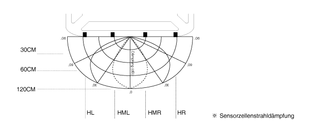
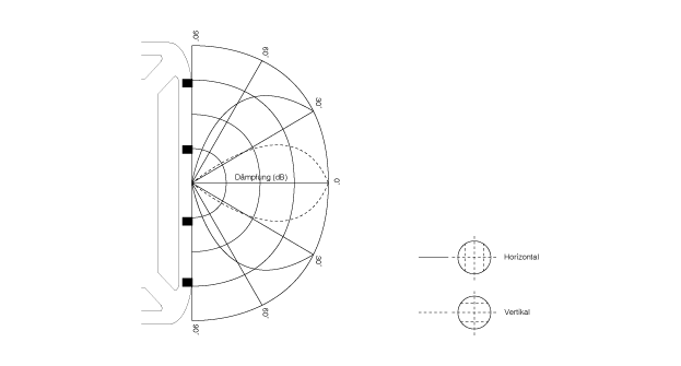
Erfassungsbereich
Measurement condition - PVC rod (diameter 75 mm, length 1 m), normal temperature
Abstand zwischen Erfassungsobjekten (Messung direkt vor dem Sensor)
61 cm ~ 120 cm: ± 15 cm
31 cm ~ 60 cm: ± 15 cm
Up to 30 cm: ± 10 cm
Horizontal detection range
Vertikaler Erfassungsbereich
Abstandsmessung
Direct measurement
Übertragung und Empfang werden mit einem Sensor ausgeführt
(Ausführung für die einzelnen Sensoren RL, RCL, RCR, RR)
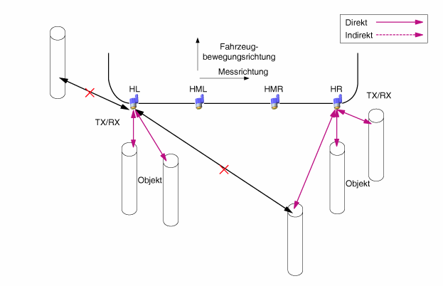
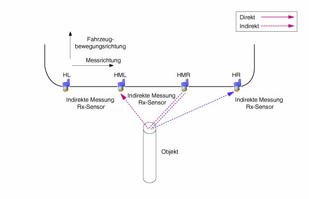
Indirect measurement
(RCL → RL, RCL → RCR, RCR → RCL, RCR → RR in sequence)
With two or more sensors, one sends the transmission and the others receive.
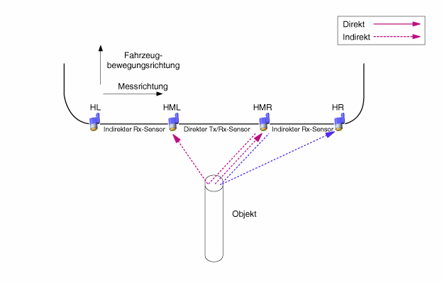
Simultaneous direct and indirect measurement
With two or three sensors, one sensor sends and receives, and the others only receive.
PDW-R warning signal
When an object is detected by the PDW-R sensor, an audible warning is triggered, e.g. by a warning buzzer. The PDW-R sensor sends the data via LIN communication to the BCM, and the BCM outputs the audible warning for the respective PDW-R sensor with priority. When a visual warning is sent to the instrument cluster, the BCM serves only as a gateway.
Processing of warning sensor/display data by BCM: For the RL/RR sensor data, the BCM processes the individual sensor data directly based on the display and warning buzzer output signals. For the warning buzzer output signal of the CL/CR sensor, the BCM processes the data centrally according to priority for both sensors.
Systembetrieb-Spez.
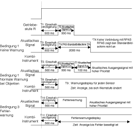
When the system is on (after turning the ignition on and shifting into reverse), the MICOM checks all sensor channels. If a fault is found, the audible signal sounds for 300 ms after 500 ms. If a fault is found in a sensor, an audible signal corresponding to the defective sensor sounds instead of the initial start alarm. Switching to normal mode is performed as follows.
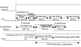
Bei eingelegtem Rückwärtsgang arbeitet das System wie folgt.
Bei nicht eingelegtem Rückwärtsgang arbeitet das System wie folgt.
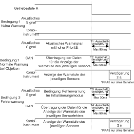
※ Der zulässige Fehlerbereich der Wellenform beträgt ±10%.
Einteilung der Spezifikation für Alarmausgabe anhand des Abstands zwischen den Sensoren
The condition logic is determined according to the priority of the alarm level as follows. (Identification sensor)
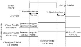
* Determination of value β
Sensor with priority Australia: α = 0 ms
1. Warning for sensor with direct priority: α < 340 ms
2. Warning for sensor with direct priority: α < 170 ms
* Determination of value β
1. Warning for sensor with direct priority: β = 1700 ms.
2. Warning for sensor with direct priority: β = 1700 ms.
3. Warning for sensor with direct priority: β = 700 ms
Die Alarmsteuerung über die Abstandserkennung funktioniert wie folgt:
First warning range (81–120 cm)
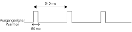
Second warning range (41 cm - 80 cm)
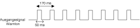
Third warning range (up to 40 cm)

Visual alarm display specification
When the transmission is shifted into the R position, the indicator lamps on the instrument cluster respond as shown in the following illustrations.
Wenn das System ein Objekt erfasst, wird die entsprechende Anzeige umgehend eingeschaltet. Wenn ein Objekt während der PDW-R-Erfassung verschwindet, bleibt die Anzeige noch 2 s an, bevor sie erlischt.
(Wenn aber vom Alarm der dritten Stufe zum Status Kein Alarm gewechselt wird, schaltet sich der Alarm der dritten Stufe 2 s lang ein und geht dann aus.)
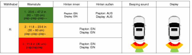
Es wird nur die erfasste Position von Hindernissen angezeigt.
At the third-level alarm, the display flashes at intervals of one second.
In normal alarm mode, integrated display RCR/RCL
Communication Standard
This section defines the communication between the PDW-R and the BCM.
The PDW-R sends the detection result for an object and the sensor diagnostic result to the BCM. Based on this data, the BCM evaluates the alarm condition.
Die Anzeige zeigt die Übertragungsposition und die Alarmdaten; im Alarmmodus haben die nächsten Einträge bzw. Alarme bei DATA Priorität.
(Example: If RL is the first alarm and RR is the third, the RR alarm has priority.)
Test yourself
A quick Kia Stonic quiz: every answer comes with an explanation and a link to the manual page.