Integrated Memory Seat (IMS)
Specifications
Specifications
| Item | Specifications |
| Rated Voltage | 12 V DC |
| Operating Voltage | 9–16 V DC |
| Operating Temperature Range | -22 to 167°F (-30 to 75°C) |
| Dark Current | Max. 1.2 mA |
Components and Component Location
Component Location
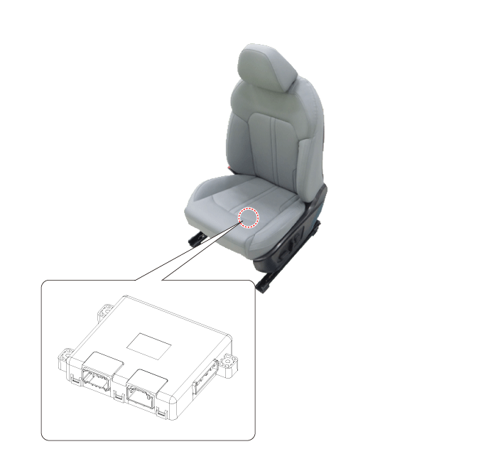
| 1. Integrated Memory Seat (IMS) Unit |
Circuit Diagrams
Connector and Terminal Function
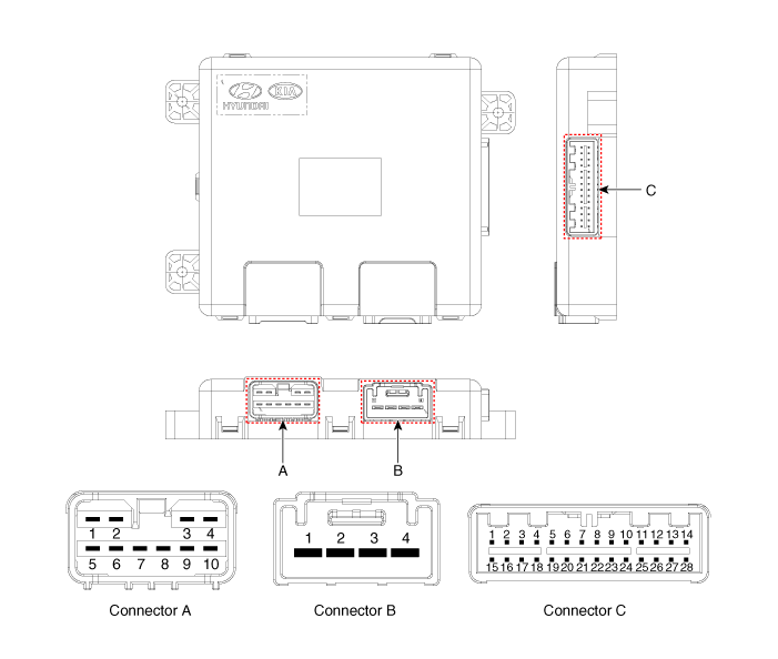
| Pin | Function | ||
| Connector A | Connector B | Connector C | |
| 1 | - | Battery (+) | Slide Switch Signal (Forward) |
| 2 | Tilt Motor (Forward) | Battery (+) | Tilt Switch Signal (Forward) |
| 3 | Rear Height Motor (Up) | Ground | Front Tilt Switch Signal (Up) |
| 4 | Slide Motor (Forward) | Ground | Rear Height Switch Signal (Up) |
| 5 | - | - | |
| 6 | Tilt Motor (Backward) | B-CAN (High) | |
| 7 | Front Tilt Motor (Up) | B-CAN (Low) | |
| 8 | Front Tilt Motor (DOWN) | - | |
| 9 | Rear Height Motor (Down) | Driver Lumbar Motor (Mid) | |
| 10 | Slide Motor (Backward) | Slide Sensor | |
| 11 | - | ||
| 12 | - | ||
| 13 | Seat Position Sensor Power | ||
| 14 | IGN1 | ||
| 15 | Slide Switch Signal (Backward) | ||
| 16 | Tilt Switch Signal (Backward) | ||
| 17 | Front Tilt Switch Signal (Down) | ||
| 18 | Rear Height Switch Signal (Down) | ||
| 19 | - | ||
| 20 | Ground | ||
| 21 | - | ||
| 22 | - | ||
| 23 | Driver Lumbar Motor (Def) | ||
| 24 | - | ||
| 25 | - | ||
| 26 | - | ||
| 27 | - | ||
| 28 | Battery (+) | ||
Repair Procedures
Removal
Disconnect the negative battery cable.
Remove the power front seat assembly.
(Refer to Body - "Front Seat Assembly")
Disconnect the IMS unit (A) connectors.

Remove the IMS unit (A) by loosening the mounting screws.
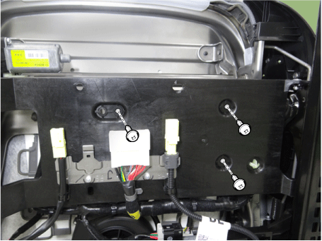
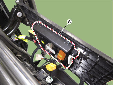
Installation
Install in the reverse order of removal.
Inspection
In the body electrical system, faults can be quickly diagnosed using the Korean Diagnostic System (KDS).
The Diagnostic System (KDS) provides the following information.
Self-diagnosis: check for malfunction and diagnostic trouble code (DTC).
Current Data: Check the system input/output status.
Operation check: Check the operating status of the system.
Special Function: Control of other functions, including parameter setting and zero point adjustment.
Select "Vehicle Model" and "Power Seat Module (PSM)" to inspect. Use the tester to inspect the vehicle.
Select the "Current Data" menu to view the current input/output data status.
Input/output data for sensors related to the Power Seat Module (PSM) can be inspected.
To forcibly activate the input value of the module under test, select the "Activation Test" option.
Test yourself
A quick Kia Optima DL3 quiz: every answer comes with an explanation and a link to the manual page.