Chassis
Brake booster
In this manual: Chassis
~4min read
F4R or K4J or K4M or K9K
Tightening torques |
|
| brake booster mounting bolt | 2.1 daN.m |
| battery cover screw | 0.4 daN.m |

Anticipate brake fluid flow to prevent damage to mechanical parts and bodywork around the brake system.
REMOVAL
- Position the vehicle on a two-post lift.
- Remove the engine covers.
- Disconnect the battery, starting with the negative terminal.
- Remove the master cylinder (Mechanical controls chapter, Master cylinder, page 37A-1).
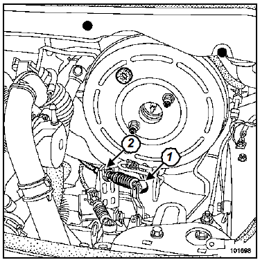
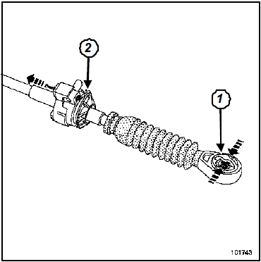
- Remove:
- the upper gearshift control ball joint (1),
- the cable sheath stop at (2) of the gearshift control cable.
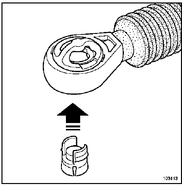
Any damage to the gearshift control cable retaining clip requires its replacement (Mechanical controls chapter).
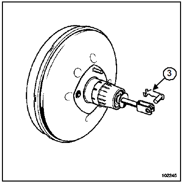
- Remove the brake pedal clevis pin (3) from the brake booster pushrod inside the passenger compartment.
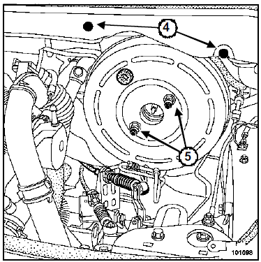
- Remove:
- the mounting clips (4) of the water box bulkhead,
- the brake booster mounting bolts (5).
INSTALLATION
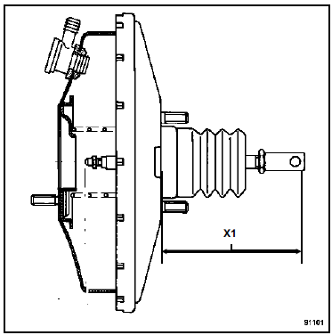
- Before refitting, check the dimension:
- for left-hand drive vehicles: (X1) = 163.7 mm,
- for right-hand drive vehicles: (X1) = 133.2 mm.
- Refit in the reverse order of removal.
- Tighten the brake booster mounting bolts to torque (2.1 daN.m).
Connect the battery; carry out the necessary relearn procedures (Chapter Battery).
- Refit the master cylinder (Mechanical controls chapter, Master cylinder, page 37A-1).
- Torque the battery cover screws (0.4 daN.m).
- Bleed the brake circuit (General chapter, Bleeding the brake circuit, page 30A-5).
F9Q
Tightening torques |
|
| brake booster mounting bolt | 2.1 daN.m |
| gearshift control cable bracket mounting bolt | 2.1 daN.m |
| EGR valve mounting bolts | 0.9 daN.m |
| battery cover screw | 0.4 daN.m |

Anticipate brake fluid flow to prevent damage to mechanical parts and bodywork around the brake system
REMOVAL
- Position the vehicle on a two-post lift.
- Remove the engine covers.
- Disconnect the battery, starting with the negative terminal.
- Remove the master cylinder (Mechanical controls chapter, Master cylinder, page 37A-1).
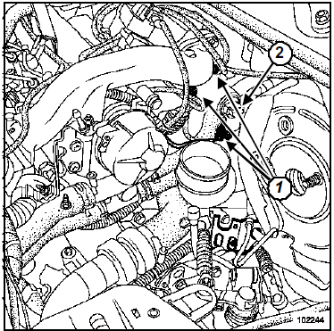
CAUTION Do not touch the gearbox selector spool.
- Remove:
- the exhaust gas recirculation valve mounting bolts (1),
- the exhaust gas recirculation valve (2),
- the gearshift control ball joints.
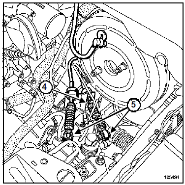
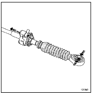
- Remove:
- the gearshift control ball joints (5),
- the cable sheath stop bracket mounting bolts (4),
- the cable sheath stop bracket.
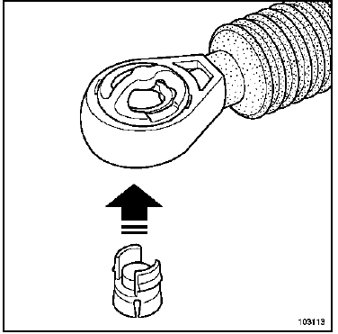
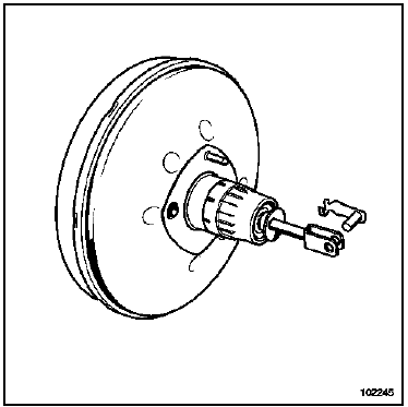
- Remove the brake pedal clevis pin from the brake booster pushrod, from inside the passenger compartment.
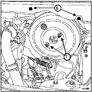
- Remove:
- the mounting clips (6) of the water box bulkhead,
- the brake booster mounting bolts (7), engine compartment side.
INSTALLATION
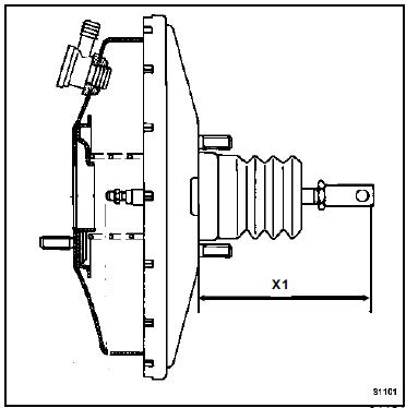
- Before refitting, check the dimension:
- for left-hand drive vehicles: (X1) = 163.7 mm,
- for right-hand drive vehicles: (X1) = 133.2 mm.
- Refit in the reverse order of removal.
- Tighten to the following torques:
- the brake booster mounting bolts (2.1 daN.m),
- the gearshift control cable bracket mounting bolts (2.1 daN.m),
- the exhaust gas recirculation valve mounting bolts (0.9 daN.m).
- Refit the master cylinder (Mechanical controls chapter, Master cylinder, page 37A-1).
Connect the battery; carry out the necessary relearn procedures (Chapter Battery).
- Torque the battery cover screws (0.4 daN.m).
- Bleed the brake circuit (General chapter, Bleeding the brake circuit, page 30A-5).
Test yourself
A quick Renault Megane quiz: every answer comes with an explanation and a link to the manual page.
Was this page helpful?