Chassis
Clutch master cylinder
In this manual: Chassis
~4min read
Essential special tooling |
|
| Tool 1596 | 24 mm socket for removal and refitting of accelerometer |
Tightening torques |
|
| battery cover screws (left-hand drive) | 0.4 daN.m |
| clutch pedal bracket nuts | 2.1 daN.m |
| battery cover screws (right-hand drive) | 0.4 daN.m |

REMOVAL
- Disconnect the battery, starting with the negative terminal.
- Remove:
- the engine covers,
- the battery,
- the battery tray.
- Disconnect the injection ECU.
- Remove the injection ECU.
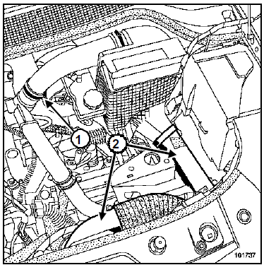
- Loosen the air hose clamp (1).
- Remove:
- the air sleeves (2),
- the air filter housing.
- Drain the brake fluid reservoir until the level is below the master cylinder supply port.
JH3 or JR5
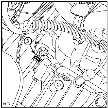
- Lift the clip (3).
- Pull the clutch control pipe out by one notch.
ND0
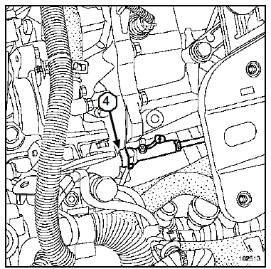
- Press the clip (4) by hand while pulling on the pipe.
Do not pull on the clip. Any handling error requires replacing the pipe.
- Pull the clutch control pipe out by one notch.
- Place a rag under the bleed port.
- Operate the pedal by hand (to empty the master cylinder and the pipe).
LEFT-HAND DRIVE
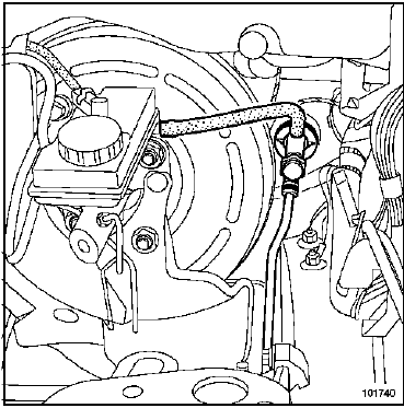
- Place a rag under the port (5).
- Disconnect the pipe from the brake fluid reservoir.
- Fit plugs to the openings.
- Place a rag under the master cylinder.
- Remove the connector clip from the master cylinder (6).
- Disconnect the pipe.
- Fit plugs to each port.
- Disconnect the master cylinder pushrod from the clutch pedal in the passenger compartment.
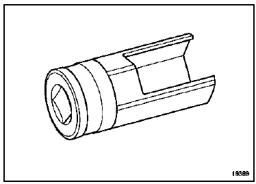
- Remove the bulkhead master cylinder in the engine compartment by turning it a quarter turn clockwise (bayonet fixing) using tool (Emb. 1596).
RIGHT-HAND DRIVE
Note: The clutch master cylinder is mounted on the clutch pedal. Remove the pedal-master cylinder assembly to extract the pedal and the master cylinder.- Drain the brake fluid reservoir until the level is below the master cylinder supply port using a syringe.
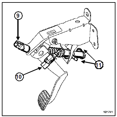
- Remove the grey (9) travel start switch by turning it a quarter turn.
- Disconnect the connector of switch (9).
- Remove the green (10) end-of-travel switch by turning it a quarter turn.
- Disconnect the connector of switch (10).
- Place a rag under the master cylinder.
- Remove the connector clips from the master cylinder (11).
- Disconnect the pipes.
- Fit plugs to the openings.
- Remove the clutch master cylinder pushrod from the pedal.
- Remove the four nuts from the "pedal" assembly.
- Remove the "pedal - master cylinder" assembly.
- Remove the bulkhead master cylinder by turning it a quarter turn clockwise (bayonet fixing) using tool (Emb. 1596).
INSTALLATION
LEFT-HAND DRIVE
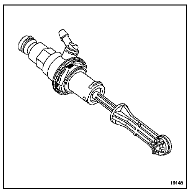
- Check the condition of the seals.
- Refit in the reverse order of removal.
- Lubricate both ends of the supply line with brake fluid to ease fitting onto the brake fluid reservoir outlet.
- The transmitter has a polarising key, so there is only one possible position.
WARNING: Do not use the outlet as a support when fitting.
- Connect the transmitter ball joint to the clutch pedal.
- Pull the end of the sensor fully to position it at minimum.
The pedal position sensor has automatic adjustment that adapts to the pedal position.
- Refit in the reverse order of removal.
- Bleed the clutch control (see Chapter Mechanical Controls, Bleeding the Clutch Circuit, page 37A-39).
- Check that the clutch system operates correctly.
Connect the battery; carry out the necessary relearn procedures (Chapter Battery).
- Tighten the battery cover screws to torque (left-hand thread) (0.4 daN.m).
RIGHT-HAND DRIVE
- Check the condition of the seals.
- Refit in the reverse order of removal.
- Tighten the clutch pedal bracket nuts to torque (2.1 daN.m).
- Pull the end of the sensor fully to position it at maximum.
The pedal position sensor has automatic adjustment that adapts to the pedal position.
- Refit in the reverse order of removal.
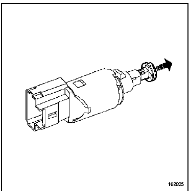
- Position the switches in their housings and turn them one quarter turn clockwise.
- Reconnect the two clutch pedal switches.
- Bleed the clutch control (see Chapter Mechanical Controls, Bleeding the Clutch Circuit, page 37A-39).
- Check that the clutch system operates correctly.
Connect the battery; carry out the necessary relearn procedures (Chapter Battery).
- Tighten the battery cover screws to torque (right-hand thread) (0.4 daN.m).
Test yourself
A quick Renault Megane quiz: every answer comes with an explanation and a link to the manual page.
Was this page helpful?