Clutch Components
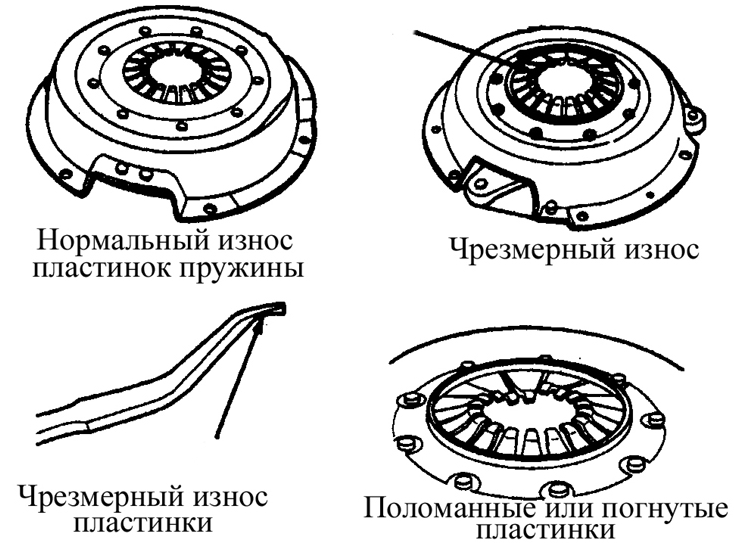
Damage
* Dust produced by wear of the clutch friction material and deposited on the clutch components contains asbestos, which is hazardous to health. Do not blow or breathe in this dust. Do not use gasoline or petroleum-based solvents to remove this dust. Use brake system cleaning fluid to flush it into a drain pan. Then wipe the clutch components dry with a rag. Place used rags and cleaning fluid in a sealed, labeled container and dispose of them properly.
Removal
PROCEDURE
1. To gain access to the clutch components, the transmission is usually removed from the vehicle. If you are removing the engine for overhaul, it is recommended to inspect the clutch components and replace any worn parts. In any case, the cost of new clutch components is much less than the time and effort required to gain access to them by removing the engine or transmission, so it is recommended to replace all clutch components unless they are new or in nearly perfect condition. The following operations assume that the transmission is removed to gain access to the clutch components.
2. Remove the release cylinder (see subsection 8.2.4). Suspend it so that it does not interfere with the work; it is not necessary to disconnect the hose.
3. Remove the transmission from the vehicle (see subsection 7.1.5 and subsection 7.2.8). Install a support under the engine while the transmission is removed from the vehicle. It is also recommended to use a hoist to support the engine from above.
* If you use a jack, place a wooden block or board between the jack and the engine oil pan to distribute the load.
The oil return tube connection is located very close to the bottom of the oil pan. If the pan is bent or deformed, the engine may not receive sufficient lubrication.
4. The clutch release fork and release bearing may be left installed on the transmission for now.
5. To support the clutch driven disc during removal, insert the clutch alignment tool into the disc hub.
6. Carefully inspect the flywheel and pressure plate and locate the index marks. These marks are usually an X, an O, or a white letter. If you cannot find them, make your own marks so that the pressure plate and flywheel can be reinstalled in their original positions.
7. Gradually loosen the pressure plate-to-flywheel bolts. Loosen the bolts diagonally, loosening each one a little at a time, until the spring pressure is fully released. Then, while holding the pressure plate, remove all the bolts and take off the pressure plate and clutch driven disc.
Inspection
PROCEDURE
1. Usually, if the clutch has problems, they are caused by wear of one of the clutch cover components. However, all clutch components must be inspected.
2. Inspect the flywheel for cracks, signs of overheating, scoring, or other damage. If the flywheel is not badly damaged, its surface can be resurfaced at a machine shop to make it flat and smooth. The flywheel removal procedure is described in subsection 3.1.1.14.
3. Inspect the clutch disc friction material. It must project above the rivet heads by at least 1.587 mm. Check the clutch disc for loose rivets, distortion, cracks, broken springs, or other damage. Normally, the clutch driven disc is replaced every time the clutch is disassembled, so if it is not new or in perfect condition, replace it.
4. The release bearing must be replaced together with the clutch disc (see subsection 8.2.2).
5. Inspect the friction surface of the pressure plate and the diaphragm spring fingers. If the pressure plate surface is scored or has any other damage, replace the pressure plate. Also check it for distortion, cracks, and other obvious damage. A glazed surface can be removed with fine sandpaper. When replacing the pressure plate, either a new or a remanufactured plate may be installed.
Installation
PROCEDURE
1. Before installation, thoroughly wipe the flywheel and pressure plate surfaces. It is very important that there is no oil or grease on these surfaces or on the friction material of the clutch disc. Handle these components only with clean hands.
2. Install the clutch disc and pressure plate while holding the clutch disc with the clutch alignment tool. Make sure the clutch disc is installed correctly (most discs are marked flywheel side or similar). If there is no marking, install the disc with the damper springs or cushioning plates facing the transmission.
3. Start the pressure plate mounting bolts into the flywheel, but do not fully tighten them yet.
4. Center the clutch disc accurately in the clutch cover by inserting the alignment tool through the disc hub into the recess in the crankshaft. Move the tool up and down or from side to side until it seats in place. Tighten the pressure plate-to-flywheel bolts gradually and in a crisscross pattern, alternating between bolts, to avoid distorting the clutch cover. After all bolts are tightened, torque them to the specification given in the Specifications section at the beginning of this chapter. Remove the alignment tool.

5. Apply high-temperature grease to the inner groove of the release bearing (figure left). Also apply a small amount of grease to the contact surfaces of the clutch release fork (figure right) and to the installation point of the bearing on the transmission input shaft (figure left).
6. Install the clutch release bearing (refer to Subsection 8.2.2).
7. Install the transmission, clutch release hydraulic cylinder and all other components removed earlier, tightening their fasteners to the specified torque.
Test yourself
A quick Toyota Corolla quiz: every answer comes with an explanation and a link to the manual page.