Axle Shaft - GENERAL INFORMATION
Drive power is transmitted from the transaxle to the wheels through the axle shafts. The inner ends of the axle shafts are attached to the differential side gears through a splined connection. The outer ends of the axle shafts are attached to the wheel hubs through a splined connection and secured with nuts.
Constant velocity (CV) sliding joints are installed on the inner ends of the axle shafts, which allow both axial and angular movement. Each inner CV joint consists of a tripod with three rollers and a joint housing (which acts as the outer race), in which the tripod can move back and forth as the axle shaft moves up and down with the wheel. The joints can be disassembled and cleaned if the boot is damaged; however, if any joint component is damaged, the entire joint must be replaced. The outer CV joints are Rzeppa-type universal joints and consist of ball bearings in which the balls rotate between the inner race and the outer housing, which allows angular but not axial movement. Outer joints must be cleaned, inspected, and refilled with new grease, but they cannot be disassembled. If an outer joint is damaged, it must be replaced together with the axle shaft (outer joints are sold only as a complete axle shaft assembly).
Joint boots must be inspected regularly for damage or grease leakage. Torn boots must be replaced immediately, otherwise the joints may be damaged. To replace a boot, the axle shaft must be removed.
* Slip-on boots are available that can be installed without removing the axle shaft. This is a fairly convenient alternative; however, the axle shaft must be removed and the joint disassembled and cleaned to check whether moisture or dirt has entered the joint, which would accelerate wear.
The main signs that a joint is worn or damaged are, in addition to grease leakage, knocking when turning, during acceleration, and vibration at high speeds.
To check joint and axle shaft wear, grip the axle shaft and try to rotate it in both directions while holding the joint housings. If you feel free play, this indicates worn splines or joints. Also inspect the axle shaft for cracks, dents, and deformation.
Removal
PROCEDURE
1. Disconnect the negative battery cable.
* If your vehicle's stereo has an anti-theft code system, make sure you know the radio activation code before disconnecting the battery.
2. Apply the parking brake.
3. Loosen the front wheel mounting nuts, raise the vehicle and support it on stands. Remove the wheels.
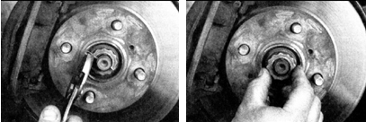
4. Remove the cotter pin (photo left) and remove the cap from the axle shaft nut (photo right).

5. Unscrew and remove the axle shaft nut and washer. To prevent the hub from rotating, insert a pry bar between the wheel mounting bolts and place the other end of the pry bar against the floor pan or underbody of the vehicle.
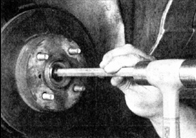
6. To remove the axle shaft from the hub splines, strike the end of the shaft with a brass-faced hammer or use a copper drift.
* If excessive force is applied to the axle shaft, the shaft or transaxle may be damaged. If the axle shaft is tightly fitted in the hub splines and cannot be driven out, it will be necessary to remove the brake disc (refer to Subsection 9.7) and press the
axle shaft out using a two-legged puller after performing step 8.
7. Remove the engine splash shields (refer to Subsection 3.1.2.4.1). Place a drain pan under the transmission to catch the oil that will drain when the axle shaft is removed.
8. Remove the nuts and bolts securing the ball joint to the suspension arm, then lower the suspension arm to disconnect it from the ball joint (refer to Subsection 10.5).
9. Turn the steering knuckle and pull the axle shaft out of the hub. Do not allow the outer end of the axle shaft to hang from the inner CV joint, as this will cause it to fail. Suspend the outer end of the axle shaft with wire if necessary.
10. Carefully pull the inner end of the axle shaft out of the transmission by pushing out the inner CV joint.
11. The axle shaft seal replacement procedure is described in the chapter covering the transmission.
Installation
PROCEDURE
1. Installation is the reverse of removal. Pay attention to the following points during installation.
2. Push the inner end of the axle shaft firmly into the transaxle so that the retaining ring on the end of the inner joint engages the groove on the differential side gear.
3. Tighten the axle shaft nut to the specified torque (refer to Subsection 8.1), then install the nut cap and a new cotter pin.
4. Install the wheel and start the wheel mounting nuts, lower the vehicle to the ground, and tighten the nuts to the specified torque (refer to Subsection 10.1).
5. Check the oil level in the transaxle or differential housing and add oil as necessary to the specified level (refer to Subsection 2.3).
Test yourself
A quick Toyota Corolla quiz: every answer comes with an explanation and a link to the manual page.