Installation
1. INSTALL INJECTORS AND DELIVERY PIPES
NOTICE:
- Be careful not to drop the injectors when installing the delivery pipes.
- Since the O-ring may be stuck to the injector, do not put a side load on it at the removal.

(a) Install a new grommet to each injector.
(b) Apply a light coat of gasoline to new O-rings and install them to each injector
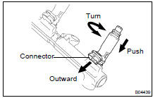
(c) While turning the injector clockwise and counterclockwise, push it to the delivery pipes. Install the 8 injectors.
(d) Position injector connector outward.
(e) Place the 4 spacers and 8 new insulators on the intake manifold.
(f) Place the 2 delivery pipes and the injectors assemblies on the lower intake manifold.
(g) Temporarily install the 4 nuts.
(h) Install the front fuel pipe with the bolt, the 4 new gaskets and the 2 union bolts.
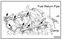
Torque: 39 N·m for union bolts 7,5 N·m for bolt
(i) Install the bolt holding the clamp on the fuel return pipe to the LH delivery pipe.
Torque: 7,5 N·m

(j) Check that the injectors rotate smoothly.
HINT: If injectors do not rotate smoothly, the probable cause is incorrect installation of O-rings. Replace the O-rings in that case.
(k) Position the injector connector outward.
(l) Tighten the 4 nuts holding the delivery pipes to the lower intake manifold.
Torque: 21 N·m
(m) Connect the 8 injectors connectors.
2. INSTALL ENGINE WIRE TO LH DELIVERY PIPE
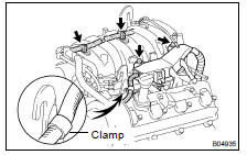
Install the 2 wire clamps on the engine wire to the brackets on the delivery pipe.
3. INSTALL ENGINE WIRE PROTECTOR
(a) Connect the engine wire clamp to the No.1 engine hanger.
(b) Install the engine wire protector with the 2 bolts.
(c) Connect the PCV hose to the PCV valve.
(d) Connect VSV EVAP to the upper intake manifold.
(e) Install the No.1 V-bank cover bracket to the upper intake manifold.
(f) Install the No.2 V-bank cover bracket to the upper intake manifold.
(g) Install the No.3 V-bank cover bracket to the upper intake manifold.
(h) Install the No.4 V-bank cover bracket to the upper intake manifold.
4. INSTALL FUEL PRESSURE PULSATION DAMPER (SF-1 )
5. INSTALL INTAKE AIR CONNECTOR
6. INSTALL V-BANK COVER
Test yourself
A quick Toyota Land Cruiser quiz: every answer comes with an explanation and a link to the manual page.