High-Pressure Fuel Pump Injection Timing
PROCEDURE
The fuel pump injection timing can be checked and adjusted either on the engine removed from the vehicle or installed in the vehicle. The camshaft drive belt must be tensioned. Bosch Pump
Bosch Fuel Pump Control Linkage 1 – threaded plug; 2 – fuel supply rod; 3 – lock washer; 4 – maximum speed adjustment screw; 5 – lever; 6 – idle speed adjustment screw; 7 – bolt; 8 – pin; 9 – lock washer; 10 – washer; 11 – starting device rod
The starting device rod must not be extended. PROCEDURE
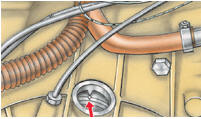
1. Turn the crankshaft so that the TDC mark on the flywheel aligns with the boss on the clutch housing.
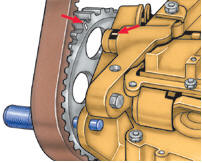
2. Align the mark on the pump drive gear with the mark on the bracket. 3. Remove the threaded plug 1 (see fig. Bosch Fuel Pump Control Linkage) from the center of the rear pump cover and install dial indicator with extension VAG 2066 in its place. Screw in the indicator until the pointer starts to move. Set the indicator to zero. 4. Screw in the indicator until it shows a preload of 2.5 mm. 5. Turn the crankshaft counterclockwise (opposite to the direction of engine rotation) until the indicator pointer stops moving. 6. Screw in the indicator until the preload is approximately 1 mm and set it to zero. 7. Turn the crankshaft counterclockwise (opposite to the direction of engine rotation) until the TDC marks on the flywheel and clutch housing align. The indicator must show 0.83–0.97 mm for engines JR, RA and SB, and 0.93–1.07 mm for engines JP and 1V. 8. If the indicator readings are not within these limits, adjust the injection timing. To do this, loosen the pump mounting bolts at the front bracket 14 and rear bracket 12 (see fig. Valve Timing Drive Components). To loosen the lower pump mounting bolt to bracket 14, turn the pump drive gear 15 so that the bolt aligns with the hole in the gear. Change the pump angle relative to the cylinder block so that the indicator shows 0.90±0.02 mm for engines JR, RA and SB, and 1.00±0.02 mm for engines JP and 1V. 9. Tighten the pump mounting bolts to 25 N·m. 10. Remove the indicator and install the threaded plug, replacing the plug sealing ring beforehand. Tighten the plug to 15 N·m. If leakage occurs, tighten the plug further. Maximum permissible torque 25 N·m. CAV Pump PROCEDURE 1. Fully pull out the starting device control knob on the instrument panel. 2. Screw the dial indicator into extension VAG 3071, then back it out by half a turn. This prevents the indicator from seizing.
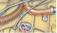
3. Turn the crankshaft so that the mark on the flywheel aligns with the boss on the clutch housing.
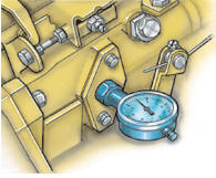
4. Remove the threaded plug from the side of the pump and install a dial indicator with extension as shown in the figure in its place. Screw in the indicator until it shows a preload of 2 mm. 5. Turn the crankshaft counterclockwise (opposite to the direction of engine rotation) by 20–30 mm. 6. Continue turning the crankshaft counterclockwise (opposite to the direction of engine rotation) until the indicator shows its lowest value. 7. Check the alignment of the TDC marks on the flywheel and clutch housing. A misalignment of ±2 mm is permissible. 8. If the TDC marks do not align, adjust the injection timing. To do this, turn the crankshaft until the TDC marks align. Loosen the fuel pump mounting bolts at the front and rear brackets. Change the pump angle relative to the cylinder block so that the indicator shows its lowest value. 9. Tighten the pump mounting bolts to 25 N·m. 10. Remove the indicator and install the threaded plug.
Test yourself
A quick Volkswagen Golf quiz: every answer comes with an explanation and a link to the manual page.