Input Shaft (Four-Speed Transmission)
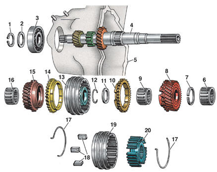
Input Shaft 1 – snap ring; 2 – adjusting washer; 3 – bearing; 4 – input shaft; 5 – transmission case; 6 – bearing; 7 – snap ring; 8 – 4th gear; 9 – needle bearing; 10 – synchronizer blocking ring; 11 – washer; 12 – snap ring; 13 – synchronizer; 14 – synchronizer blocking ring; 15 – 3rd gear; 16 – needle bearing; 17 – spring; 18 – synchronizer key; 19 – synchronizer sliding sleeve; 20 – synchronizer hub
Flower delivery, Ray Tsvetov, Vologda, among the flowers.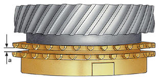
Measuring the Clearance Between the Gear and the Synchronizer Blocking Ring
Disassembly PROCEDURE 1. Remove snap ring 7. 2. Remove 4th gear 8 and needle bearing 9. 3. Remove synchronizer blocking ring 10. 4. Remove washer 11 and snap ring 12. 5. Press off 3rd gear 15 together with synchronizer 13 and blocking ring 14. 6. Remove needle bearing 16. Assembly PROCEDURE 1. Check the clearance between 3rd gear 15 and blocking ring 14, and between 4th gear 8 and blocking ring 10. To do this, insert the blocking ring into the cone of the corresponding gear and measure the gap with a feeler gauge (see figure Measuring the Clearance Between the Gear and the Synchronizer Blocking Ring). Clearance "a" must be 1.1–1.7 mm; maximum permissible clearance is 0.5 mm. 2. Lubricate needle bearing 16 (see figure Input Shaft) and install it on shaft 4. 3. Install 3rd gear 15. 4. Install synchronizer blocking ring 14. 5. Press on synchronizer 13 so that the slot in the synchronizer hub faces the 4th gear, and the synchronizer keys engage the slots of the blocking ring. 6. Install washer 11 and snap ring 12. 7. Install synchronizer blocking ring 10, making sure the synchronizer keys engage the slots of the blocking ring. 8. Lubricate needle bearing 9 and install it on shaft 4. 9. Install 4th gear 8. 10. Install the snap ring.
Test yourself
A quick Volkswagen Golf quiz: every answer comes with an explanation and a link to the manual page.