Input shaft (four-speed transmission type 020)
PROCEDURE

Input shaft 1 – bushing; 2 – input shaft; 3 – needle bearing; 4 – 3rd gear; 5 – blocking ring; 6 – synchronizer; 7 – snap ring; 8 – blocking ring; 9 – needle bearing; 10 – 4th gear; 11 – washer; 12 – bearing; 13 – snap ring; 14 – adjusting shim
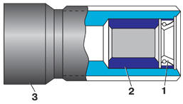
Input shaft bushing with sealing ring 1 – sealing ring; 2 – bushing; 3 – input shaft

Special tool for adjusting the input shaft 1 – special bracket; 2 – threaded rod; 3 – bolt; 4 – nut; 5 – bushing; 6 – input shaft; 7 – clutch housing
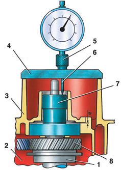
Adjusting the Input Shaft Axial Play 1 – input shaft; 2 – 4th gear wheel; 3 – transmission housing; 4 – support; 5 – dial gauge; 6 – dial gauge plunger; 7 – special bushing; 8 – washer; a – measured axial play
Disassembly PROCEDURE 1. Press off ball bearing 12 (see illustration Input Shaft). 2. Remove 4th gear wheel 10. 3. Remove needle bearing 9. 4. Remove synchronizer blocking ring 8. 5. Remove snap ring 7. 6. Remove synchronizer 6. 7. Remove synchronizer blocking ring 5. 8. Remove 3rd gear wheel 4. 9. Remove needle bearing 3. 10. Check the clearance between the clutch pushrod and seal ring 1 (see illustration Input Shaft Bushing and Seal Ring). If there is clearance, replace seal ring 1. 11. Press bushing 2 with seal ring 1 out of input shaft 3. Assembly Warning Lubricate all parts before assembly.
PROCEDURE 1. Press bushing 2 and new seal ring 1 into input shaft 3. Seal ring must be recessed 0.8–1.3 mm from the end face of the input shaft. 2. Install needle bearing 3 (see illustration Input Shaft). 3. Check the clearance between blocking rings 5 and 8 and their corresponding gears 4 and 10 (see subsection 5.2.2.1). 4. Install 3rd gear wheel 4. 5. Install blocking ring 5. 6. Install synchronizer with the chamfer on the hub facing the 3rd gear wheel, making sure the synchronizer keys engage the slots of the blocking ring. 7. Install snap ring 7. 8. Install blocking ring 8, making sure the synchronizer keys engage the slots of the blocking ring. 9. Install needle bearing 9. 10. Install 4th gear wheel 10. Input Shaft Adjustment PROCEDURE 1. Install the special tool on the clutch housing (see illustration
Special tool for input shaft adjustment). Bracket 1 is bolted with bolts 3 to clutch housing 7. Threaded rod 2 has nut 4 and sleeve 5 bearing against input shaft 6. 2. Turn nut 4 to move the input shaft until the clearance between 2nd gear wheel of output shaft and 3rd gear wheel of input shaft is 1 mm (measure with feeler gauge). 3. Lock nut 4 in this position. 4. Install 3.5 mm washer if washer 11 is missing (see illustration
Input Shaft) in this configuration. The washer must be installed on the shaft with radial clearance. 5. Install special bushing 7 (VW549) on input shaft 1 (see illustration Adjusting the Input Shaft Axial Play). The bushing 7 can be made based on the dimensions of the ball bearing, input shaft and transmission housing. 6. Install support 4. 7. Install dial gauge 5 with plunger 6. 8. Move bushing 7 up and down and read the dial gauge to determine the axial play "a". 9. Select an adjusting washer of two sizes, 0.3 and 0.6 mm, according to the measured axial play. Measured axial play, mm / Adjusting washer thickness, mm: 0 – 0.46: no washer required; 0.47 – 0.75: 0.3; 0.76 – 1.04: 0.6; 1.05 – 1.45: 0.6 + 0.3
Test yourself
A quick Volkswagen Golf quiz: every answer comes with an explanation and a link to the manual page.