Transmission Assembly (five-speed transmission)
PROCEDURE

Installing the Transmission Shafts 1 – reverse gear; 2 – 1-2 shift fork rod; 3 – 3-4 shift fork rod; 4 – output shaft; 5 – input shaft; 6 – special tool
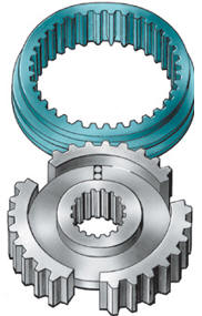
5th Gear Synchronizer
Assembly PROCEDURE 1. Install shaft 68 (see figure Transmission Type 085) of the reverse gear together with reverse gear 67. 2. Install the 1-2 shift fork with rod into the groove of the output shaft synchronizer sliding sleeve. 3. Install the output shaft 4 (see figure Installing the Transmission Shafts) and the 1-2 shift fork rod 2 simultaneously, lifting the reverse gear with wire hook 6. 4. Install the 3-4 shift fork with rod into the groove of the input shaft synchronizer sliding sleeve. 5. Lift output shaft 4 with rod 2 and install the input shaft with 3-4 shift fork rod 3, lifting the reverse gear with wire hook 6. 6. Tighten bolt 11 (see figure Transmission Internal Shifting Mechanism) securing the reverse gear shaft. 7. Install the reverse gear shift fork rod 3 (see figure Removing the Shift Shaft) with fork. 8. Tighten bolt 10 (see figure Transmission Internal Shifting Mechanism). 9. Install the 5th gear shift fork rod 2 (see figure Removing the Shift Shaft). 10. Tighten bolt 9 (see figure Transmission Internal Shifting Mechanism). 11. Place all shift forks in the neutral position. 12. Install bracket 4 of the shift lever and bushing 3. 13. Tighten bolt 2. 14. Install shift lever 1 with spring into bracket 4. 15. Drive in shift shaft 6 and install plug 5 flush with the transmission case surface. 16. Install connecting bushing 8 (see figure Clutch Housing) and tighten bolt 9. 17. Adjust the relative position of shift lever 1 (see figure Transmission Internal Shifting Mechanism) and connecting bushing 8 (see figure Clutch Housing) (see subsection 5.3.4). 18. Install the differential. 19. Install locating pins 10 into clutch housing 11 (see figure Transmission Case). 20. Apply sealant to the mating surface of clutch housing 11. 21. Join transmission case 5 and clutch housing 11. 22. Tighten bolts 14 to torque 25 N·m. 23. Install a new seal 3 (see figure Transmission Type 085) into bushing 4, lubricating the sealing lip with grease. Warning The axle shaft flanges differ from each other. The sealing lip diameter on the left side is 57 mm, and on the right side is 48 mm.
24. Press bushing 4 into the clutch housing. 25. Install flange 2 of the half shaft with spring 5, washer 6 and spacer ring 7. 26. Lock the half shaft flange with a screwdriver and tighten bolt 1 to 25 N·m. 27. Press 5th gear pinion 64 onto the input shaft, with the pinion collar facing the bearing. 28. Install washer 27 onto the output shaft. 29. Lubricate and press the inner race of needle bearing 26 onto the shaft. 30. Install needle bearing 26. 31. Install 5th gear pinion 25 onto the output shaft, with the pinion collar facing the bearing. 32. Install synchronizer blocking ring 24 with spring 23. 33. Press synchronizer hub 22 on, with the hub collar facing 5th gear pinion and the blocking ring lugs engaging the hub slots. 34. Install snap ring 21. 35. Install the sliding sleeve onto the synchronizer hub, with the tapered splines on the sleeve facing 5th gear pinion and aligned with the wider spline gaps of the hub (see illustration Synchronizer, 5th gear). 36. Engage 5th gear. 37. Engage 2nd gear using the shift lever, locking the shafts. 38. Install a new bolt 66 (see illustration Transmission type 085) with spring washer 65 on the end of the input shaft and tighten to 40 N·m. 39. Move all shift forks to the neutral position. 40. Remove the 5th gear synchronizer sliding sleeve. 41. Install lever 5 (see illustration 5th gear shift fork) onto the 5th gear shift fork rod. 42. Install 5th gear shift fork 2 and 5th gear synchronizer sliding sleeve 4 at the same time. Caution: From 1986 a new bolt 1 is installed to secure the 5th gear shift fork. The thread of the old and new bolts is different.
43. Install bushing 3 and tighten bolt 1. 44. Turn bolt 1 until the end face of the sliding sleeve is flush with the end face of the synchronizer hub. 45. Engage 5th gear. 46. Tighten bolt 1 so that fork 2 has no play in the groove of the sliding sleeve. 47. Loosen bolt 1 so that a small clearance forms between fork 2 and the groove of the sliding sleeve. 48. Tighten the locknut. 49. Install cover 1 (see illustration Transmission housing) of the transmission with a new gasket 4. 50. Tighten bolts 2 to 8 N·m.
Test yourself
A quick Volkswagen Golf quiz: every answer comes with an explanation and a link to the manual page.