Gearbox Disassembly (five-speed gearbox)
PROCEDURE
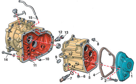
Gearbox housing 1 – cover; 2 – bolt; 3 – washer; 4 – gasket; 5 – gearbox housing; 6 – drain plug; 7 – reverse light switch; 8 – plug; 9 – magnet; 10 – pin; 11 – clutch housing; 12 – bushing; 13 – oil seal; 14 – bolt; 15 – valve

5th gear shift fork 1 – bolt; 2 – 5th gear shift fork; 3 – bushing; 4 – 5th gear synchronizer sliding sleeve; 5 – lever
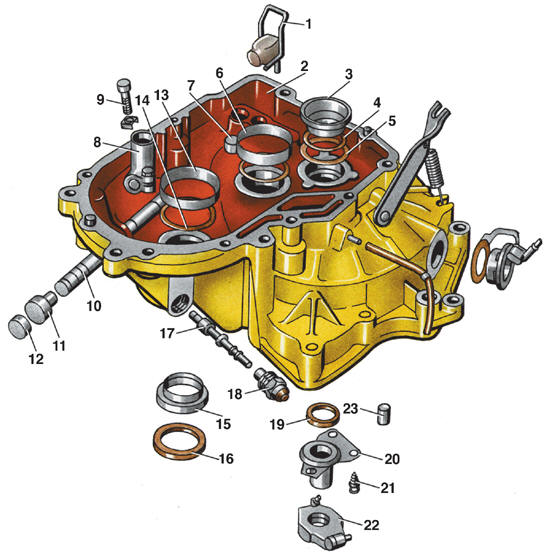
Clutch housing 1 – bracket; 2 – clutch housing; 3 – outer race of tapered roller bearing; 4 – adjusting shim; 5 – washer; 6 – outer race of tapered roller bearing; 7 – adjusting shim; 8 – connecting bushing; 9 – bolt; 10 – gear shift rod; 11 – bushing; 12 – oil seal; 13 – outer race of tapered roller bearing; 14 – adjusting shim; 15 – bushing; 16 – oil seal; 17 – speedometer drive shaft; 18 – threaded bushing; 19 – O-ring; 20 – guide bushing; 21 – bolt; 22 – release bearing; 23 – pin
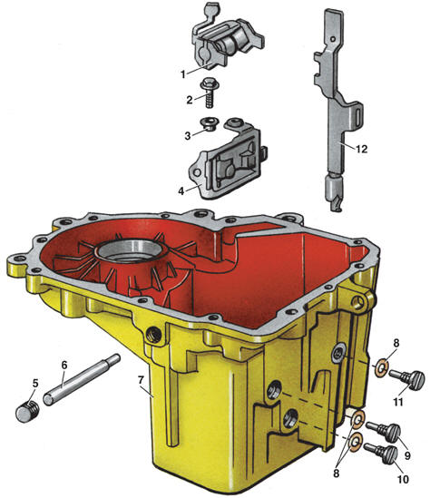
Gearbox internal shift mechanism 1 – shift lever; 2 – bolt; 3 – bushing; 4 – bracket; 5 – plug; 6 – shift shaft; 7 – gearbox housing; 8 – washer; 9 – bolt securing 5th gear shift fork rod; 10 – screw securing reverse shift fork rod; 11 – screw securing reverse idler gear shaft; 12 – rod
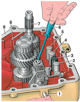
Removing the shift shaft 1 – shift shaft; 2 – 5th gear shift fork rod; 3 – reverse shift fork rod; 4 – 1st–2nd gear shift fork rod; 5 – 3rd–4th gear shift fork rod; 6 – screwdriver; 7 – input shaft; 8 – output shaft; 9 – gearbox housing
Disassembly. PROCEDURE 1. Clean the gearbox of dirt and rinse with water, taking care to keep water out of the housings. 2. Insert a screwdriver into the hole of flange 2 (see figure Gearbox type 084) and rest it against the rib of clutch housing 6 to lock the flange against rotation. Warning: The axle shaft flanges have different lengths. The left flange is 84.5 mm long and the right flange is 89.6 mm long. It is recommended to mark the flanges before removal.
3. Unscrew bolt 1 using an open-end wrench. 4. Remove axle shaft flange 2 from the clutch housing using two screwdrivers. 5. Remove spring 3, washer 4 and spacer ring 5. 6. Remove the axle shaft flange on the other side of the gearbox (see steps 2–5). Note: From 1986, hex-head axle shaft flange bolts were replaced with bolts having a cylindrical head with a hex socket.
7. Unscrew the three bolts 2 (see figure Gearbox housing). 8. Remove gearbox cover 1 and gasket 4. 9. Engage 5th gear. 10. Loosen the locknut located under fork 2 (see figure 5th gear shift fork). 11. Unscrew bolt 1 and remove it together with bushing 3. 12. Remove fork 2 and 5th gear synchronizer sliding sleeve 4 together. 13. Reinstall 5th gear synchronizer sliding sleeve 4. 14. Engage 5th gear using the synchronizer and 2nd gear using the gear shift lever, thereby locking the gearbox shafts from rotating. 15. Unscrew bolt 66 (see figure Gearbox type 085). 16. Remove 5th gear synchronizer sliding sleeve 4 (see figure 5th gear shift fork). 17. Remove snap ring 21 (see figure Gearbox type 085). 18. Press off 5th gear 25 together with synchronizer 22, blocking ring 24 and needle bearing 26. 19. Hook support washer 27 and remove it together with the inner race of the needle bearing. 20. Press 5th gear 64 off input shaft 62. 21. Remove lever 5 (see figure 5th gear shift fork) from the 5th gear shift fork rod. 22. Unscrew bolts 14 (see figure Gearbox housing). 23. Separate gearbox housing 5 from clutch housing 11. 24. Remove the differential. 25. Unscrew threaded bushing 18 (see figure Clutch housing) and remove speedometer drive shaft 17. 26. Unscrew the reverse light switch. Warning: If the connecting bushing or the internal shift lever is removed, adjustment must be performed during installation.
27. Unscrew bolt 9. 28. Remove connecting sleeve 8. 29. Remove plug 5 (see illustration Gearbox internal shift mechanism). 30. Drive out shift shaft 6. 31. Remove shift lever 1. 32. Unscrew bolt 2 and remove bushing 3. 33. Remove shift lever bracket 4. 34. Unscrew bolt 9 securing the 5th gear selector fork rod and screw 10 securing the reverse gear selector fork rod. 35. Remove 5th gear selector fork rod 2 (see illustration Removing gear shift shaft) and reverse gear selector fork rod 3. 36. Unscrew screw 11 (see illustration Gearbox internal shift mechanism) securing the reverse idler gear shaft. 37. Remove the input shaft 7 (see illustration Removing gear shift shaft) and output shaft 8 together with the reverse gear and shaft, and shift fork rods 4 and 5 for 1st-2nd and 3rd-4th gears from the gearbox housing.
Test yourself
A quick Volkswagen Golf quiz: every answer comes with an explanation and a link to the manual page.