Transmission Assembly (four-speed transmission)
PROCEDURE

Reverse Gear Shaft Installation a – distance from the end of the reverse gear shaft to the transmission case flange
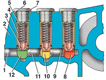
Locking Mechanism 1 – plug; 2 – transmission case; 3 – locking sleeve; 4 – guide sleeve; 5 – spring; 6 – gasket; 7 – plug; 8 – 3rd-4th shift fork rod; 9 – locking pin; 10 – 1st-2nd shift fork rod; 11 – locking pin; 12 – reverse gear shift fork rod

Clearance between Reverse Gear Fork and 1st-2nd Shift Fork 1 – reverse gear fork; 2 – 1st-2nd shift fork
PROCEDURE 1. Press in the reverse gear shaft, maintaining dimension a = 83.3 mm from the shaft end to the transmission case flange (see figure Reverse Gear Shaft Installation). 2. Press bearing 6 (see figure Transmission Case) of the countershaft into transmission case 22, with the cage side facing the case. 3. Insert locking pin 9 (see figure Locking Mechanism) into the hole of transmission case 2. 4. Push back the shift lever and lock it with M16 nut 6 (see
figure Special Plate Installation). 5. Install rod 14 (see figure Transmission Case) with 1st-2nd shift fork 21, countershaft 15 and reverse gear 19. 6. Press countershaft 15 into the inner race of bearing 6, making sure shift fork rod 14 and reverse gear 19 do not jam. 7. Install adjusting shim 5 and snap ring 4. 8. Adjust countershaft axial play if any of the following parts were replaced: clutch housing, transmission case, countershaft or countershaft tapered roller bearings. 9. Install snap ring 4 without adjusting shim 5. 10. Measure the clearance between snap ring 4 and the inner race of bearing 6 with a feeler gauge. 11. Select adjusting shim 5 so that the clearance is 0–0.05 mm. 12. Install mainshaft 17 and rod 16 with 3rd-4th shift fork 20 into the transmission case, making sure locking pin 9 (see figure Locking Mechanism) is located between rods 8 and 10. Lift reverse gear 19 (see figure Transmission Case) using the tool (see figure Special Tool). 13. Install the special plate (see figures Special Plate and Special Plate Installation). 14. Press in bearing 30 (see figure Transmission Case) until it stops, with the cage side facing the transmission case. 15. Install adjusting shim 31 and snap ring 32. 16. Adjust mainshaft axial play if any of the following parts were replaced: clutch housing, transmission case, mainshaft or mainshaft tapered roller bearings, similarly to the countershaft adjustment (see paras.
9–11). 17. Remove the special plate. 18. Remove nut M16, releasing the gear lever. 19. Insert locking pin 11 (see illustration Locking mechanism). 20. Install rod 11 (see illustration Transmission housing) of the reverse gear shift fork and reverse gear shift fork 13. 21. Turn rod 11 and engage reverse gear shift fork 13 with reverse gear wheel 19. 22. Tighten bolt 24 with washer 23 so that distance a (see illustration Clearance between reverse gear shift fork and 1st–2nd gear shift fork) between reverse gear shift fork 13 and 1st–2nd gear shift fork 21 is 1.3–2.8 mm. 23. Assemble locking bushing 25 (see illustration Transmission housing) with spring 26 and guide bushing 27, and insert the three sets into the transmission housing (see illustration Locking mechanism). 24. Install gaskets 6 and tighten plugs 7. 25. Tighten plug 1. 26. Install adjusting shims 3 and 33 (see illustration Transmission housing) according to the markings made earlier. 27. Select adjusting shims 3 and 33 if one of the following parts was replaced: clutch housing or transmission housing, input or output shaft, or tapered roller bearings of the shafts. To do this, with the relevant bearing fully pressed in, measure with a dial indicator the distance between the rear face of the transmission housing and the outer face of the bearing. 28. Install a new gasket 2 and cover 1. 29. Tighten bolts 34 to 25 N·m. 30. Carry out test shifts. All gears must engage easily and smoothly. 31. Install differential assembly. 32. Install dowel pins. 33. Apply “D3” sealant to the mating surfaces of the clutch housing and transmission housing, or install a new gasket (depending on version). 34. Install magnet in clutch housing. 35. Set shift forks to neutral position. 36. Join clutch housing to transmission housing, making sure the shift rod pin engages with the gear lever. 37. Tighten bolts evenly in a diagonal sequence to 25 N·m. 38. Insert half-shaft flanges 2 (see illustration Transmission type 084) with spacer ring 5, thrust washer 4 and spring 3 into the splines of the differential bevel gears. 39. Lock half-shaft flanges with a screwdriver and tighten bolts 1 to 25 N·m. 40. Install reverse light switch. Measured distance, mm / Shim thickness 0.14 – 0.18 0.45 0.19 – 0.23 0.50 0.24 – 0.28 0.55 0.29 – 0.33 0.60 0.34 – 0.38 0.65 0.39 – 0.43 0.70 0.44 – 0.48 0.75 0.49 – 0.53 0.80 0.54 – 0.58 0.85 0.59 – 0.63 0.90 0.64 – 0.68 0.95 0.69 – 0.73 1.00 0.75 – 0.79 1.05 0.80 – 0.84 1.10 0.85 – 0.89 1.15 0.90 – 0.94 1.20 0.95 – 0.99 1.25 1.00 – 1.04 1.30
Test yourself
A quick Volkswagen Golf quiz: every answer comes with an explanation and a link to the manual page.