Disassembly of the gearbox (four-speed gearbox)
PROCEDURE
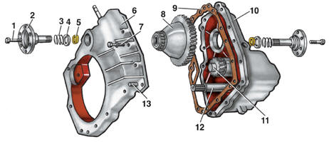
Gearbox type 084 1 – bolt; 2 – axle shaft flange; 3 – spring; 4 – washer; 5 – spacer ring; 6 – clutch housing; 7 – bolt; 8 – differential; 9 – gasket; 10 – gearbox housing; 11 – output shaft; 12 – input shaft; 13 – pin
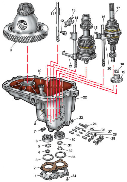
Gearbox housing 1 – rear cover; 2 – gasket; 3, 33 – large adjusting washer; 4, 32 – snap ring; 5, 31 – small adjusting washer; 6, 30 – bearing; 7 – plug; 8 – reverse light switch; 9 – differential; 10 – shift lever; 11 – reverse gear fork rod; 12 – reverse gear fork rod pin; 13 – reverse gear fork; 14 – 1st-2nd gear shift fork rod; 15 – output shaft; 16 – 3rd-4th gear shift fork rod; 17 – input shaft; 18 – snap ring; 19 – reverse gear; 20 – 3rd-4th gear shift fork; 21 – 1st-2nd gear shift fork; 22 – gearbox housing; 23 – washer; 24 – bolt; 25 – detent sleeve; 26 – spring; 27 – guide sleeve; 28 – gasket; 29 – detent plug; 34 – bolt
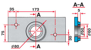
Special plate
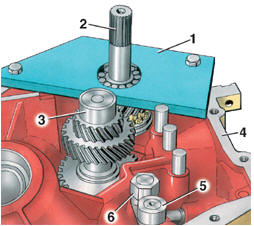
Installing the special plate 1 – special plate; 2 – input shaft; 3 – output shaft; 4 – gearbox housing; 5 – shift lever; 6 – M16 nut
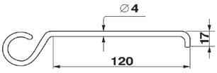
Special tool
PROCEDURE 1. Clean the gearbox of dirt and wash with water, protecting the housings from water ingress. 2. Insert a screwdriver into the hole of axle shaft flange 2 (see fig. Gearbox type 084) and brace it against the rib of clutch housing 6 to lock the flange from turning. Note: The axle shaft flanges have different lengths. The left flange is 84.5 mm and the right flange is 89.6 mm. It is recommended to mark the flanges before removal.
3. Unscrew bolt 1 using an open-end wrench. 4. Remove axle shaft flange 2 from the clutch housing using two screwdrivers. 5. Remove spring 3, washer 4 and spacer ring 5. 6. Remove the axle shaft flange on the other side of the gearbox (see steps 2–5). Note: From 1986, hex-head axle shaft flange bolts were replaced with bolts having a cylindrical head with a hex socket.
7. Unscrew the reverse light switch 8 (see figure Transmission Case). 8. Remove the bolts and separate the clutch housing from the transmission case. 9. Remove the differential 8 (see figure Transmission Type 084) assembly from the transmission case. 10. Remove the magnet from the clutch housing. 11. Move shift forks 21 and 20 (see figure Transmission Case) to the neutral position. 12. Unscrew the three shift rod detent plugs 29, remove gaskets 28, and remove guide bushings 27, springs 26 and detent bushings 25. 13. Unscrew plug 7, then remove the pins when removing the corresponding shift fork rods. 14. Remove bolts 34 and remove the rear cover 1 of the transmission case. 15. Remove gasket 2. 16. Remove adjusting rings 3 and 33, marking them for installation on the corresponding shafts. 17. Remove the snap ring 32 of the input shaft. 18. Remove the small adjusting washer 31 and mark it. 19. Unscrew bolt 24 securing reverse shift fork 13. 20. Remove reverse shift fork rod 11 and reverse shift fork 13. 21. Install the special plate on transmission case 8 (for dimensions see figure Special Plate) in the specified position (see figure Special Plate Installation), locking the input shaft. 22. Push shift lever 5 aside and lock it in this position using M16 nut 6. 23. Press out the rear ball bearing 30 (see figure Transmission Case) of the input shaft. 24. Remove the special plate 1 (see figure Special Plate). 25. Tilt the input shaft 17 (see figure Transmission Case), disengaging its gears from the output shaft gears 15, and remove input shaft 17 and rod 16 with 3-4 gear shift fork 20, while lifting reverse gear 19 (see figure Transmission Case) with a special wire tool (see figure Special Tool). 26. Remove nut 6 (see figure Special Plate Installation) securing the shift lever. 27. Remove the snap ring 4 (see figure Transmission Case) of the output shaft. 28. Remove adjusting washer 5 and mark it. 29. Press out output shaft bearing 6. 30. Remove snap ring 18. 31. Remove output shaft 15, rod 14 with 1-2 gear shift fork 21, and reverse gear 19. 32. Remove the clutch mechanism from the clutch housing (see subsection 4.2.1). 33. Remove the seal and press out the input shaft roller bearing from the clutch housing (if necessary). 34. Press out the output shaft roller bearing from the clutch housing (if necessary). 35. Unscrew the sleeve and remove the speedometer drive gear. 36. Press out the reverse gear shaft (if necessary).
Test yourself
A quick Volkswagen Golf quiz: every answer comes with an explanation and a link to the manual page.