Repairing wiring harnesses

Note
Observe the general notes on repairing the vehicle electrical system
Notes on repairing airbag and belt tensioner wiring
In addition to the general repair of wiring harnesses, the following procedures must be observed when repairing wiring for the airbag and belt tensioner system:

WARNING!
- The airbag and belt tensioner system can fail.
- Faulty repairs to the airbag and belt tensioner wiring harness can lead to a malfunction of the occupant protection system.
- For repairs to the airbag and belt tensioner wiring harness, only the contacts, connectors and wires intended for this purpose may be used → Electronic Parts Catalog (ETKA).

Note
- Wires of the airbag and belt tensioner wiring harness may only be repaired with the Wiring Harness Repair Kit -VAS 1978 B- and its predecessors.
- Observe the general notes on repairing the vehicle electrical system.
- Observe the labels on the vehicle that indicate components with high voltage. Before carrying out repair work, the residual voltage must be discharged → Body; Body Assembly Work Interior.
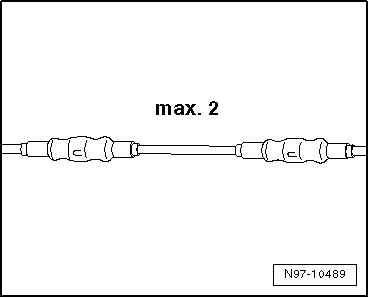
- When repairing wires of the airbag and belt tensioner system, no more than two repair points may be made. Repair points increase the electrical resistance in the wire and can trigger faults in the system's self-diagnosis.
- When repairing the airbag or belt tensioner wiring harness, the crimp connectors must always be shrunk to prevent corrosion.
- Do not rewrap the repair point into the vehicle's wiring harness, and mark the repair point clearly with yellow insulating tape.
- Repairs in the area of the airbag or belt tensioner should be made no more than 30 cm away from the nearest connector housing. Together with the marking by the yellow insulating tape, this procedure allows a quick overview of previous repairs.
- In series production, the wires to the airbag initiators have a twist with a lay length of 20 mm ±5. This lay length is ensured for series production by standard part numbers for the wire pairs and must be strictly maintained when repairing twisted wires.

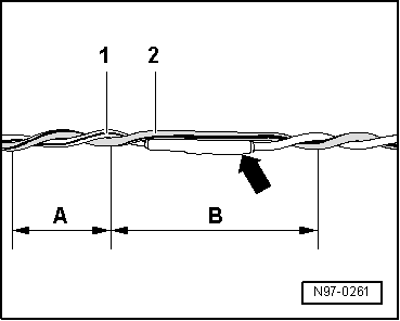
- When carrying out repairs, the wires to the airbag initiators must have the same length. When twisting wires -1- and -2-, the lay length of A = 20 mm ±5 must be strictly maintained.
- No section of wire, for example in the area of crimp connectors -arrow-, may be left untwisted over a length greater than B = 100 mm.
Repairing CAN bus wires
- The CAN bus wire is an unshielded two-wire cable -1- and -2- with a cross-section of 0.35 mm 2 or 0.5 mm 2.
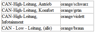
- Refer to the following table for the color coding of the CAN bus wires:

- CAN bus wires can be repaired either with repair wire of a suitable cross-section or with the twisted wires "green/yellow" or "white/yellow" from the Electronic Parts Catalog → Electronic Parts Catalog (ETKA).
- When carrying out repairs, both bus wires must be the same length. When twisting wires -1- and -2-, the lay length of A = 20 mm must be maintained.
- No section of wire may be left untwisted that is longer than B = 50 mm, for example in the area of crimp connectors -arrow-.
- Mark the repair point with yellow adhesive tape to identify a previous repair.
Replacing Antenna Cables
A new repair concept has been developed for repairing antenna cables.
Instead of a complete antenna cable, connecting cables in various lengths and different adapter cables are now offered as replacement parts.
General description:
- The replacement parts can be found in the → Parts Catalog (ETKA): Special Catalog; Electrical Connections; Original Accessories; Subgroup 35, from figure no. 035-20.
- These original replacement parts are suitable for all antenna cables to be replaced and all wire cross-sections.
- Connector housings for antenna cables are only available as a replacement part in one color, but can be used for all colors of antenna connectors.
- Replacing individual antenna connectors is not provided for in repair cases.
- The cables are to be used retroactively for all VW models, with all installed antenna cable cross-sections.
- All adapters and connecting cables are suitable for all transmit and receive signals.
- The repair concept can also be used as a test or retrofit solution.
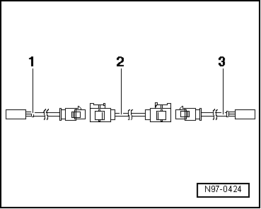
Assembly overview of an antenna cable:
Example: antenna cable from radio to antenna defective. The following cables are required for the repair:
- Adapter cable for connection to the radio. Length approx. 30 cm.
- Connecting cable, available in different cable lengths.
- Adapter cable for connection to the antenna. Length approx. 30 cm.
Installing a new antenna cable:

Note
Note that, depending on vehicle equipment, the total run of an antenna cable may be divided into sections by antenna selection control units, traffic radio control units or antenna amplifiers. Only the defective section is to be replaced.
- Disconnect the connectors of the defective antenna cable from the units.
- Determine the routing of the defective antenna cable in the vehicle and measure the total length of the antenna connection to be replaced in the vehicle.
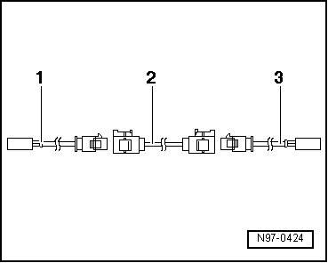
The total length of the antenna connection results from the length of the required adapter cables -1- and -3- and the connecting cable -2-.
- Subtract 60 cm from the measured total length of the antenna connection to obtain the required length of connecting cable -2- to be procured.
- Obtain the required adapter cables -1- and -3- and the connecting cable -2- in the calculated length as original replacement parts according to the Electronic Parts Catalog.
- Cut off the connectors of the defective antenna cable.
The remainder of the defective antenna cable remains in the vehicle.
- Connect adapter cables -1- and -3- to the units in the vehicle.
- Route and secure connecting cable -2- directly next to the original cable routing.

Note
Antenna cables must not be kinked or bent excessively! The bending radius must not be less than 50 mm.
- Connect the connecting cable to the adapter cables.
- Carry out a function test.
Repairing Wires with a Cross-Section up to 0.35 mm2
Required Special Tools, Test and Measuring Equipment and Auxiliary Items
- Crimping pliers, complete -VAS 1978/1 A-
- Interchangeable head, 0.35 mm² - 2.5 mm² -VAS 1978/1-1-
When repairing wires with a cross-section up to 0.35 mm2, new contacts must be crimped only with JPT contact crimping pliers -VAS 1978/9A-, or with crimping pliers (basic body) -VAS 1978/1-2- fitted with JPT contact interchangeable head -VAS 1978/9-1-. Due to the low currents of these wires in the micro- to milliamp range, incorrectly crimped contacts lead to transition resistances and cause faults or failure of the respective system. The most common applications of these contacts are:
- Lambda sensor
- Speed sensor
- Air mass meter
Using the JPT contact crimping pliers -VAS 1978/9A- or the crimping pliers (basic body) -VAS 1978/1-2- fitted with the JPT contact interchangeable head -VAS 1978/9-1- ensures the correct connection between crimp contact, wire and single-wire seal (seal). The tool must only be used for the purpose described.

Note
Repair wires are crimped with contacts in standard and gold-plated versions. The repair contact must always be the same version as the one originally fitted.
Crimping a new contact with single-wire seal
- Insert the JPT contact interchangeable head -VAS 1978/9-1- into the crimping pliers (basic body) -VAS 1978/1-2-.
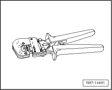
- Slide the single-wire seal onto the repair wire.

Note
The smaller diameter of the single-wire seal must point in the direction of the contact to be crimped.

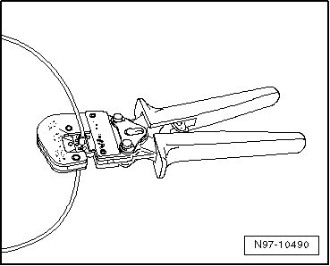
- Open the crimping pliers and insert the end of the repair wire into the stripping opening of the crimping pliers.

- Close the crimping pliers completely.
- Open the crimping pliers again and remove the stripped wire end.

- Slide the single-wire seal toward the stripped wire end until it is flush with the wire insulation.

- Insert the new crimp contact into the receptacle of the crimping pliers.

- Insert the stripped wire end with the positioned single-wire seal into the crimp contact until it contacts the "wire stop".
- Crimp the contact, wire and single-wire seal together by closing the crimping pliers completely.
- Open the crimping pliers again and remove the finished crimped contact.

A correctly made crimp is characterized by a clean crimp of the wire and the individual wire seal in contact, and has an embossed mark on the back indicating that the crimp was made properly and with the correct tool.

Wire break with single repair point
Repair point with single crimp connector
- Expose the wire to be repaired (approx. 20 cm on both sides of the repair point).
- If necessary, remove the wrapping from the wiring harness using the folding knife.

- Cut out the damaged section of wire using wire stripper -VAS 1978/3-.

Note
If the two ends of the vehicle's individual wire become too short for a repair with a single crimp connector after cutting out the damaged section, use a correspondingly long piece of repair wire with two crimp connectors.

- Strip the wire ends by 6 - 7 mm using wire stripper.

- Slide the crimp connector onto both stripped wire ends of the vehicle's individual wire and crimp it using the crimping pliers.

Note
- Be sure to use the correct crimping jaw for the crimp connector being used.
- The wire insulation must not be crimped.
After crimping, the crimp connector must be shrunk with the heat gun to prevent moisture from entering.
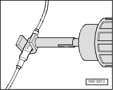
- Fit the heat shrink attachment -VAS 1978/15- to the heat gun, 220 V/ 50 Hz -VAS 1978/14-.
- Heat the crimp connector with the heat gun in the longitudinal direction from the center outwards until it is fully sealed and the adhesive emerges at the ends.

Caution!
When shrinking the crimp connectors, make sure the hot nozzle of the hot air blower does not damage other wires, plastic parts or insulation material.
Be sure to observe the operating instructions for the hot air blower!

Note
- If several wires are to be repaired, make sure the crimp connectors are not directly next to each other. To keep the wiring harness from becoming too thick, arrange the crimp connectors slightly offset.
- If the repair point was previously wrapped, the area must be rewrapped with yellow insulating tape after the repair.
- If necessary, secure the repaired wiring harness with a cable tie to prevent rattling noises while driving.

Wire break with double repair point
Repair point with inserted wire
- Expose the wire to be repaired at two points (approx. 20 cm on both sides of each repair point).
- If necessary, remove the wrapping from the wiring harness using the folding knife.
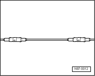
- Place the yellow repair wire next to the damaged wiring harness and cut the repair wire to the required length using wire stripper -VAS 1978/3-.
- Cut out the damaged wire section from the vehicle's individual wire.

- Strip the wire ends by 6 - 7 mm using wire stripper.
- Slide the crimp connector onto the vehicle's individual wires on one side and onto the repair wire on the other side.

- Crimp the crimp connector onto both wire ends using the crimping pliers.
- Repeat this procedure at the other wire end of the repair wire.

Note
- Be sure to use the correct crimping jaw for the crimp connector being used.
- The wire insulation must not be crimped.
After crimping, the crimp connector must be shrunk with the heat gun to prevent moisture from entering.
- Fit the heat shrink attachment -VAS 1978/15- to the heat gun, 220 V/ 50 Hz -VAS 1978/14-.

- Heat the crimp connector with the heat gun in the longitudinal direction from the center outwards until it is fully sealed and the adhesive emerges at the ends.

Caution!
When shrinking the crimp connectors, make sure the hot nozzle of the hot air blower does not damage other wires, plastic parts or insulation material.
Be sure to observe the operating instructions for the hot air blower!

Note

- If several wires are to be repaired, make sure the crimp connectors are not directly next to each other. To keep the wiring harness from becoming too thick, arrange the crimp connectors slightly offset.
- If the repair point was previously wrapped, the area must be rewrapped with yellow insulating tape after the repair.
- If necessary, secure the repaired wiring harness with a cable tie to prevent rattling noises while driving.
