Repair of Optical Fibers
The exact fault location is very difficult to find. The damaged optical fiber must be replaced by laying a new cable parallel to the defective optical fiber.

Note
- The "Guided Fault Finding" or "Guided Functions" menu items of the Vehicle Diagnostic Tester can be used to determine between which components the optical fiber is damaged.
- An optical fiber that has already been repaired can be identified by its yellow color.
Procedure:
- In the Vehicle Diagnostic Tester, select "Guided Fault Finding" or "Guided Functions" → Vehicle Diagnostic Tester.
- Prepare the optical fiber.

Caution!
Optical fibers must not be bent sharply. A bending radius of 25 mm must not be undercut.
Optical fibers must not be routed over sharp edges.
The ends of the optical fibers must not be contaminated or touched with bare fingers.
Optical fibers must not be heated.
Twisting 2 optical fibers together, or an optical fiber with a copper wire, is not permitted.
Protect connectors and connecting cables from dust. Use protective caps from the case.
Prepare the optical fiber
Required Special Tools, Test and Measuring Equipment and Auxiliary Items
- Optical Fiber Repair Kit -VAS 6223A-

- Cutting pliers -VAS 6228-

- Vehicle diagnostic tester

Caution!
Optical fibers must not be bent sharply. A bending radius of 25 mm must not be undercut.
Optical fibers must not be routed over sharp edges.
The ends of the optical fibers must not be contaminated or handled with bare fingers.
Optical fibers must not be heated.
Twisting 2 optical fibers together, or an optical fiber with a copper wire, is not permitted.
Protect connectors and connecting cables from dust. Use protective caps from the case.

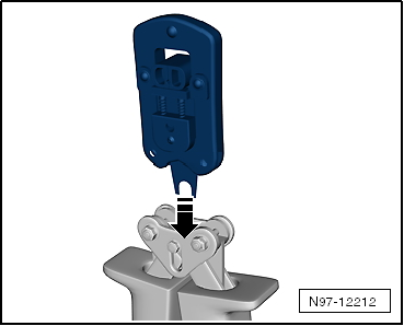
Install the tool head for optical fiber pliers -VAS 6223/1-.
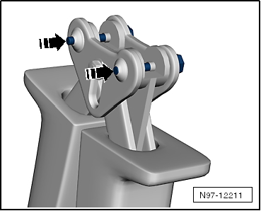
- Press out the locking pins -arrows-.
- Place the tool head on -arrow- and push the locking pins back in.
Cut the optical fiber to length.
- Determine the required length of the optical fiber.
- Open the optical fiber pliers and place the optical fiber -1- into the length-cutting holder.
- To cut the optical fiber to length, close the optical fiber pliers.
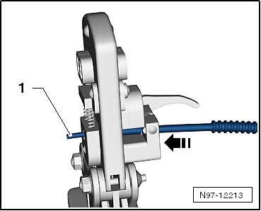
Stripping
- Open the optical fiber pliers -VAS 6223/1-.
- Move the stripping lever to the lower position -arrow-.
- Insert the optical fiber into the stripping holder.
- The optical fiber must be flush with the back of the cutting pliers.
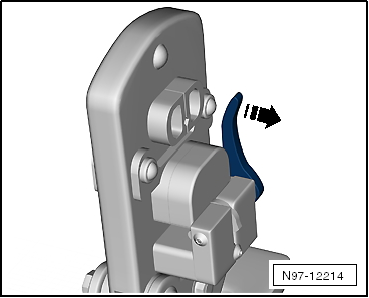
- Close the optical fiber pliers until they reach the hard stop and keep them closed.
- Swivel the stripping lever up -arrow- and remove the optical fiber.
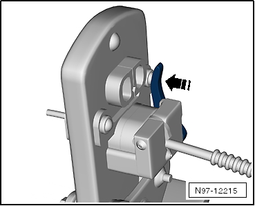
Precision cutting (produce the optical end face).
- Insert the optical fiber -1- into the cutting holder.
- The insulation must rest against the stop of the cutting station.
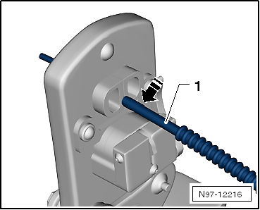
- Close the optical fiber pliers -VAS 6223/1- and remove the cable.
- Visually check the cable -1- to ensure it was cut correctly and that there is no burr on the end face.

Note
- Only place the optical fiber on an absolutely clean surface/base, or keep it in your hand.
- Use protective caps if there is a risk of contaminating the end face of the optical fiber.
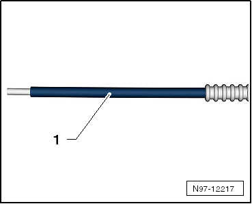
Attach a brass pin contact to the optical fiber.
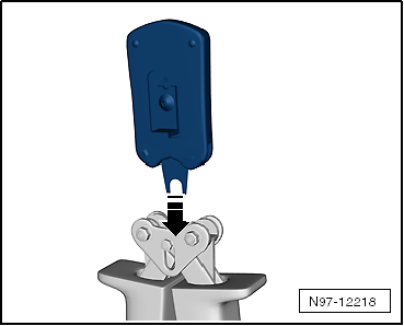
- Change the tool head -arrow-.
- Move the safety catch on the optical fiber pliers -arrow- so that the word "Stift" is visible.
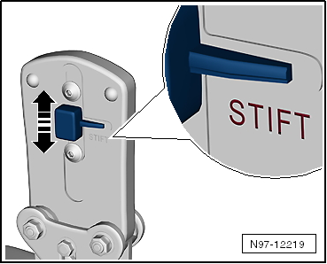
- Insert a brass pin contact -1- into the holder.
- Close the locking lever on the fiber optic cable pliers -arrow-.
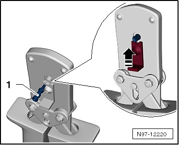
- Insert the fiber optic cable into the brass pin contact -arrow- until it reaches the spring-loaded stop, then close the fiber optic cable pliers.
- Open the fiber optic cable pliers and remove the fiber optic cable with the brass pin contact.

Caution!
Do not kink or sharply bend fiber optic cables (minimum bending radius 25 mm).

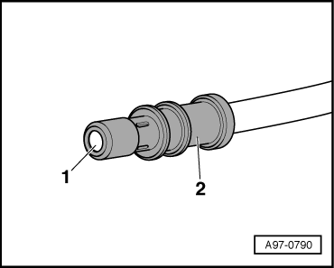
- Check that the brass pin contact -2- is correctly attached to the fiber optic cable -1-.
- 4 crimp points must be visible on the brass pin contact.
- The brass pin contact must not be removable from the fiber optic cable by hand.
- The end face of the fiber optic cable must be 0.01 ... 0.1 mm behind the brass pin contact (visual check).

Note
- Plug couplings are available for connecting fiber optic cables → Electronic Parts Catalog.
- Installing the new fiber optic cable in the wiring harness connector.
Install the corrugated tube on the fiber optic cable.
- Cut the corrugated tube to the required length.
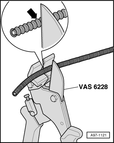
- Use cutter -VAS 6228- or a sharp knife to cut the corrugated tube.
- Never cut the corrugated tube with side cutters.
- The corrugated tube must be cut at the crest of the corrugation -arrow-, not in the trough.
- During installation, the corrugated tube must audibly snap into the fiber optic cable housing.
- Insert the fiber optic cable into the corrugated tube installation pliers -VAS 6223/10- as shown in the illustration.
- Place the corrugated tube installation pliers on the slot of the corrugated tube.
- Slide the corrugated tube installation pliers along the slot around the circumference of the corrugated tube. The fiber optic cable is thereby inserted into the corrugated tube.

Disconnecting the fiber optic cable from the wiring harness connector
Removing
- Disconnect the fiber optic cable connector from the relevant control module.
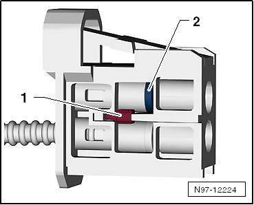
- Release the lock in the fiber optic cable connector -1- by pressing it.
- Release the secondary lock -2- with a small screwdriver.
- Remove the fiber optic cable.

Caution!
- Use the protective caps from the case to protect the fiber optic cable from dust and dirt.
- Use a new housing, as removing the fiber optic cable can damage the secondary lock.
- Observe the arrows on the base module for the "IN" and "OUT" assignment.
Installing
Installation is carried out in reverse order. Observe the following:
- Install the fiber optic cable according to its marking.

Note
- Push the corrugated tube into the connector housing until it audibly snaps in place.
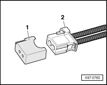
- Close the open plug connection -2- for the fiber optic cable with wiring harness connector protective cap -VAS 6223/9- -item 1-.
- The protective cap prevents contamination or mechanical damage to the end face of the fiber optic cable, which would otherwise impair light transmission.
Repairing antenna cables
Antenna cable repair kit VAS 6720
Required Special Tools, Test and Measuring Equipment and Auxiliary Items
- Antenna cable repair kit -VAS 6720-
The antenna cable repair kit -VAS 6720- allows optimal repair quality when repairing RG 174 (blue) and RTK 031 (black) antenna cables. The set contains the stripping tools and crimping tools for both antenna cables. The case also contains all necessary individual parts to re-terminate the original connectors to near-series condition. Only the zero-coded coupler (green) is required. All other connecting cables for the various infotainment systems can be found in ETKA (EL - electrical connectors) on illustration sheet 035-XX. These vehicle-specific adapter antenna cables must always be ordered separately. All individual parts for reordering can also be found on the illustration sheet mentioned above. The compartments of the consumables in the case are labeled with part numbers. The repair kit is based on the existing interchangeable heads and pliers system of VAS 1978B.

Note
Additional information: → Operating instructions, antenna cable repair kit VAS 6720
Checking the antenna cable:
Before starting the repair, use the gauge to determine which antenna cable it is.
- -1- System RG 174 = blue
- -2- System RTK 031 = gray
On both systems, the positioners of the tool heads are color-coded accordingly.
Replacing the tool head:
- Select the appropriate tool head according to the antenna cable check.
- Fully open the pliers handle.

- Unlock and pull out the two locking pins -arrows- from the pliers handle.
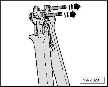
- Insert the required tool head into the pliers handle from above -arrow-.

- Lock the tool head in the pliers handle by pressing in the pins -arrows-.
Cutting the antenna cable:
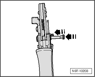
- Push the antenna cable -2- into the cutting device -1-.
- Close the tool and then open it again.
- Pull the antenna cable out of the cutting device.
Stripping the shield:


- Push the fixing pin -1- into the rotary cutting segment as far as it will go.
- Push the antenna cable -2- into the rotary cutting segment as far as it will go. The fixing pin -3- is fully visible again.

- Press the knife holder -1- against the axis of the rotary cutting segment until it engages. The gap -2- under the knife holder is fully closed.
- Hold the antenna cable so that it does not rotate with the segment.
- Turn the rotary cutting segment -3- slightly, twice in the direction of the arrow, until it turns smoothly.
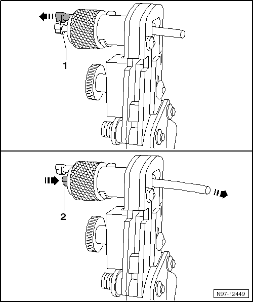
- Pull the release pin -1-. The knife holder is unlocked and detaches from the antenna cable.
- Push the fixing pin -2- into the rotary cutting segment as far as it will go. The antenna cable is pushed out of the rotary cutting segment.
- Remove the shield from the antenna cable.
- Remove insulation residue from the rotary cutting segment.
Stripping the outer jacket:

- Push the antenna cable -2- into the holder -3- in the tool head as far as the stop -1-.
- Close the tool and then open it again.
- Pull out the antenna cable -4-.
Stripping the inner insulation:

- Push the antenna cable -2- into the holder -1- in the tool head as far as the stop.
- Close the tool and then open it again.
- Pull out antenna cable -3-.
Crimp inner conductor:
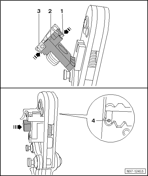
- Select the appropriate tool head according to the antenna cable check.
- Fold out pivoting positioner -2-.
- Open positioning plate -3-. The positioning plate swings upward.
- Push inner contact -1- into the pivoting positioner as far as it will go and release the positioning plate. The inner contact is secured.
- Fold the pivoting positioner back in. The inner contact -4- is positioned in the crimping head.

- Push antenna cable -1- into inner contact -2- in the crimping head. Hold the pivoting positioner in position while doing so.
- Close the tool until it opens automatically.
- Open positioning plate -3- and pull out the antenna cable.
Crimp outer conductor:

- Slide sleeve -2- and outer contact -1- over the inner conductor. The knurled contact section must be pushed under the shielding -3-, but over the aluminum foil.
- Push outer contact -4- fully on. Make sure the socket/pin is seated correctly.

- Push sleeve -3- up to the outer contact.
- Open the tool and fold out pivoting positioner -1-.
- Position the installed outer contact -2- in the middle profile of the crimping head against contact edge -4-.
- Close the tool and then open it again.
- Pull out the antenna cable.