DCT Control Module (TCM)
Circuit Diagrams
TCM Connector
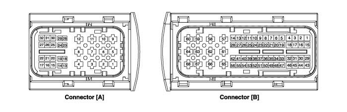
TCM Terminal Function
Connector [A]
| Pin | Description | Pin | Description |
| 1 | Clutch actuator (clutch motor 1 (odd) V-phase) | 15 | Clutch actuator (clutch motor 1 (odd) sensor ground) |
| 2 | Clutch actuator (clutch motor 2 (even) V-phase) | 18 | Clutch actuator (clutch motor 1 (odd) Hall 1) |
| 3 | Select actuator (select solenoid 2 (even) sensor ground) | 19 | Clutch actuator (clutch motor 1 (odd) power) |
| 4 | Select actuator (select solenoid 1 (odd) push) | 20 | Select actuator (select solenoid 1 (odd) sensor power) |
| 5 | Clutch actuator (clutch motor 1 (odd) U-phase) | 21 | Select actuator (select solenoid 2 (even) sensor power) |
| 6 | Clutch actuator (clutch motor 2 (even) U-phase) | 22 | Select Actuator (Select Solenoid 2 (EVEN) Sensor Output) |
| 7 | Select actuator (select solenoid 1 (odd) sensor ground) | 23 | Clutch actuator (clutch motor 2 (even) Hall 2) |
| 8 | Select actuator (select solenoid 2 (even) pull) | 24 | Clutch actuator (clutch motor 2 (even) Hall 3) |
| 9 | Clutch actuator (clutch motor 1 (odd) W-phase) | 25 | Clutch actuator (clutch motor 2 (even) sensor ground) |
| 10 | Clutch actuator (clutch motor 2 (even) W-phase) | 26 | Select Actuator (Select Solenoid 1 (ODD)_Sensor Output) |
| 11 | Select actuator (select solenoid 1 (odd) pull) | 28 | Clutch actuator (clutch motor 2 (even) Hall 1) |
| 12 | Select actuator (select solenoid 2 (even) push) | 29 | Clutch actuator (clutch motor 2 (even) sensor power) |
| 13 | Clutch actuator (clutch motor 1 (odd) Hall 2) | 30 | Select actuator (select solenoid 1 (odd) sensor ground) |
| 14 | Clutch actuator (clutch motor (odd) Hall 3) | 31 | Select actuator (select solenoid 2 (even) sensor ground) |
Connector [B]
| Pin | Description | Pin | Description |
| 3 | IGN/START input | 42 | Shift actuator (shift motor 2 (even) Hall 3) |
| 5 | "P" Position Switch Input | 43 | "M" lock switch input signal |
| 6 | Input Signal from "R" Lock Switch | 44 | CAN1 communication port 1 High |
| 7 | "D" lock switch input signal | 45 | CAN1 communication port 1 Low |
| 8 | Manual mode "Down" switch | 48 | Flexible ray high (BP) |
| 9 | Input speed sensor 2 (even) signal | 49 | Input Speed Source 1 (Odd) |
| 13 | Shift actuator (shift motor 1 (odd) Hall 2) | 50 | Input Speed Signal 1 (Odd) |
| 14 | Shift actuator (shift motor 1 (odd) Hall 3) | 54 | Shift actuator (shift motor 2 (even) sensor power) |
| 17 | Low Battery Charge VBD | 55 | Shift actuator (shift motor 2 (even) Hall 1) |
| 19 | Manual mode "Select" switch | 56 | Shift actuator (shift motor 2 (even) sensor ground) |
| 20 | Input Signal from "N" Lock Switch | 57 | Power Ground 1 for High-Current Modules |
| 21 | Manual mode "Up" switch | 58 | Power Ground 2 for High-Current Modules |
| 23 | Input speed source 2 (even) | 59 | Shift actuator (shift motor 2 (even) W-phase) |
| 24 | 5V Backup Power Output | 60 | Shift actuator (shift motor 1 (odd) W-phase) |
| 26 | Shift actuator (shift motor 1 (odd) sensor power) | 61 | Power ground 3 for high-current modules |
| 27 | Shift actuator (shift motor 1 (odd) Hall 1) | 63 | Shift actuator (shift motor 2 (even) V-phase) |
| 28 | Shift actuator (shift motor 1 (odd) sensor ground) | 64 | Shift Actuator (Shift Motor 1 (ODD)_Phase V) |
| 30 | CAN2 communication port 2 High | 65 | Motor 1 Supply Voltage from Direct Battery |
| 31 | CAN2 communication port 2 Low | 66 | Motor 2 Supply Voltage from Direct Battery |
| 34 | Flexible ray bus, BM | 67 | Shift actuator (shift motor 2 (even) U-phase) |
| 41 | Shift actuator (shift motor 2 (even) Hall 2) | 68 | Shift actuator (shift motor 1 (odd) U-phase) |
Terminal input/output signal
Connector [A]
| Pin | Description | Condition | Input/Output Value | |
| Type | Level | |||
| 1 | Clutch actuator (clutch motor 1 (odd) V-phase) | Low | Output | 0 V |
| PWM | 0 V ~ battery voltage | |||
| 2 | Clutch actuator (clutch motor 2 (even) V-phase) | Low | Output | 0 V |
| PWM | 0 V ~ battery voltage | |||
| 3 | Select actuator (select solenoid 2 (even) sensor ground) | Static on | Output | 0 V |
| 4 | Select actuator (select solenoid 1 (odd) push) | On | Output | Battery Voltage |
| Off | 0 V | |||
| 5 | Clutch actuator (clutch motor 1 (odd) U-phase) | Low | Output | 0 V |
| PWM | 0 V ~ battery voltage | |||
| 6 | Clutch actuator (clutch motor 2 (even) U-phase) | Low | Output | 0 V |
| PWM | 0 V ~ battery voltage | |||
| 7 | Select actuator (select solenoid 1 (odd) sensor ground) | Static on | Output | 0 V |
| 8 | Select actuator (select solenoid 2 (even) pull) | On | Output | Battery Voltage |
| Off | 0 V | |||
| 9 | Clutch actuator (clutch motor 1 (odd) W-phase) | Low | Output | 0 V |
| PWM | 0 V ~ battery voltage | |||
| 10 | Clutch actuator (clutch motor 2 (even) W-phase) | Low | Output | 0 V |
| PWM | 0 V ~ battery voltage | |||
| 11 | Select actuator (select solenoid 1 (odd) pull) | On | Output | Battery Voltage |
| Off | 0 V | |||
| 12 | Select actuator (select solenoid 2 (even) push) | On | Output | Battery Voltage |
| Off | 0 V | |||
| 13 | Clutch actuator (clutch motor 1 (odd) Hall 2) | High | Input | 4.5 V |
| Low | 0 V | |||
| 14 | Clutch actuator (clutch motor (odd) Hall 3) | High | Input | 4.5 V |
| Low | 0 V | |||
| 15 | Clutch actuator (clutch motor 1 (odd) sensor ground) | Ground | Ground | 0 V |
| 18 | Clutch actuator (clutch motor 1 (odd) Hall 1) | High | Input | 4.5 V |
| Low | 0 V | |||
| 19 | Clutch actuator (clutch motor 1 (odd) sensor power) | - | Power | 8.75 V |
| 20 | Select actuator (select solenoid 1 (odd) sensor power) | - | Power | 8.75 V |
| 21 | Select actuator (select solenoid 2 (even) sensor power) | - | Power | 8.75 V |
| 22 | Select Actuator (Select Solenoid 2 (EVEN) Sensor Output) | High | Input | 4 V |
| Low | 1 V | |||
| 23 | Clutch actuator (clutch motor 2 (even) Hall 2) | High | Input | 4.5 V |
| Low | 0 V | |||
| 24 | Clutch actuator (clutch motor 2 (even) Hall 3) | High | Input | 4.5 V |
| Low | 0 V | |||
| 25 | Clutch actuator (clutch motor 2 (even) sensor ground) | Ground | Ground | 0 V |
| 26 | Select Actuator (Select Solenoid 1 (ODD)_Sensor Output) | High | Input | 4 V |
| Low | 1 V | |||
| 28 | Clutch actuator (clutch motor 2 (even) Hall 1) | High | Input | 4.5 V |
| Low | 0 V | |||
| 29 | Clutch actuator (clutch motor 2 (even) supply) | - | Power | 8.75 V |
| 30 | Select actuator (select solenoid 1 (odd) sensor ground) | Ground | Ground | 0 V |
| 31 | Select actuator (select solenoid 2 (even) sensor ground) | Ground | Ground | 0 V |
Connector [B]
| Pin | Description | Condition | Input/Output Value | |
| Type | Level | |||
| 3 | IGN/START input | - | Power | 9 V < Battery Voltage < 16 V |
| 5 | "P" Position Switch Input | High | Input | 9 V < Battery Voltage < 16 V |
| Low | 0 V | |||
| 6 | Input Signal from "R" Lock Switch | High | Input | 9 V < Battery Voltage < 16 V |
| Low | 0 V | |||
| 7 | "D" lock switch input signal | High | Input | 9 V < Battery Voltage < 16 V |
| Low | 0 V | |||
| 8 | Manual mode "Down" switch | High | Input | 9 V < Battery Voltage < 16 V |
| Low | 0 V | |||
| 9 | Input speed sensor 2 (even) signal | High | Input | 0.448 V |
| Low | 0.224 V | |||
| 13 | Shift actuator (shift motor 1 (odd) Hall 2) | High | Input | 4.5 V |
| Low | 0,8 | |||
| 14 | Shift actuator (shift motor 1 (odd) Hall 3) | High | Input | 4.5 V |
| Low | 0,8 | |||
| 17 | Low Battery Charge VBD | - | Power | 9 V < Battery Voltage < 16 V |
| 18 | Paddle shifter down signal | High | Input | 9 V < Battery Voltage < 16 V |
| Low | 0 V | |||
| 19 | Shift Lever Selector Switch | High | Input | 9 V < Battery Voltage < 16 V |
| Low | 0 V | |||
| 20 | Input Signal from "N" Lock Switch | High | Input | 9 V < Battery Voltage < 16 V |
| Low | 0 V | |||
| 21 | Manual mode "Up" switch | High | Input | 9 V < Battery Voltage < 16 V |
| Low | 0 V | |||
| 23 | Input speed source 2 (even) | - | Power | 8.75 V |
| 24 | 5V Backup Power Output | - | Power | 5V |
| 26 | Shift actuator (shift motor 1 (odd) sensor power) | Power | 8.75 V | |
| 27 | Shift actuator (shift motor 1 (odd) Hall 1) | High | Input | 4.5 V |
| Low | 0.8 V | |||
| 28 | Shift actuator (shift motor 1 (odd) sensor ground) | Ground | Ground | 0 V |
| 30 | CAN2 communication port 2 High | Write/Home | CAN line | Recessive: 2.5 V |
| Dominant: 3.5 V | ||||
| 31 | CAN2 communication port 2 Low | Write/Home | CAN line | Recessive: 2.5 V |
| Dominant: 1.5 V | ||||
| 34 | Flexible ray bus, BM | Idle | CAN line | Standby: 2.5 V |
| Differential | Differential: 2.0 V/3.0 V | |||
| 41 | Shift actuator (shift motor 2 (even) Hall 2) | High | Input | 4.5 V |
| Low | 0.8 V | |||
| 42 | Shift actuator (shift motor 2 (even) Hall 3) | High | Input | 4.5 V |
| Low | 0.8 V | |||
| 43 | "M" Position Switch Input Signal | High | Input | 9 V < Battery Voltage < 16 V |
| Low | 0 V | |||
| 44 | CAN1 communication port 1 High | Idle | CAN line | |
| Differential | ||||
| 45 | CAN1 communication port 1 Low | Idle/Diff. | Write/Home | Recessive: 2.5 V |
| Dominant: 3.5 V | ||||
| 48 | Flexible Beam High (BP) | Idle/Diff. | CAN line | Standby: 2.5 V |
| Differential: 2.0 V / 3.0 V | ||||
| 49 | Input Speed Source 1 (Odd) | - | Power | 8.75 V |
| 50 | Input Speed Signal 1 (Odd) | High | Input | 0.448 V |
| Low | 0.224 V | |||
| 54 | Shift actuator (shift motor 2 (even) sensor power) | - | Power | 8.75 V |
| 55 | Shift actuator (shift motor 2 (even) Hall 1) | High | Input | 4.5 V |
| Low | 0.8 V | |||
| 56 | Shift actuator (shift motor 2 (even) sensor ground) | Ground | Ground | 0 V |
| 57 | Power Ground 1 for High-Current Modules | Ground | Ground | 0 V |
| 58 | Power Ground 2 for High-Current Modules | Ground | Ground | 0 V |
| 59 | Shift actuator (shift motor 2 (even) W-phase) | Low | Output | 0 V |
| PWM | 0 V ~ battery voltage | |||
| 60 | Shift actuator (shift motor 1 (odd) W-phase) | Low | Output | 0 V |
| PWM | 0 V ~ battery voltage | |||
| 61 | Power ground 3 for high-current modules | Ground | Ground | Ground |
| 63 | Shift actuator (shift motor 2 (even) V-phase) | Low | Output | 0 V |
| PWM | 0 V ~ battery voltage | |||
| 64 | Shift Actuator (Shift Motor 1 (ODD)_Phase V) | Low | Output | 0 V |
| PWM | 0 V ~ battery voltage | |||
| 65 | Motor 1 Supply Voltage from Direct Battery | - | Power | 9 V < Battery Voltage < 16 V |
| 66 | Motor 2 Supply Voltage from Direct Battery | - | Power | 9 V < Battery Voltage < 16 V |
| 67 | Shift actuator (shift motor 2 (even) U-phase) | Low | Output | 0 V |
| PWM | 0 V ~ battery voltage | |||
| 68 | Shift actuator (shift motor 1 (odd) U-phase) | Low | Output | 0 V |
| PWM | 0 V ~ battery voltage | |||
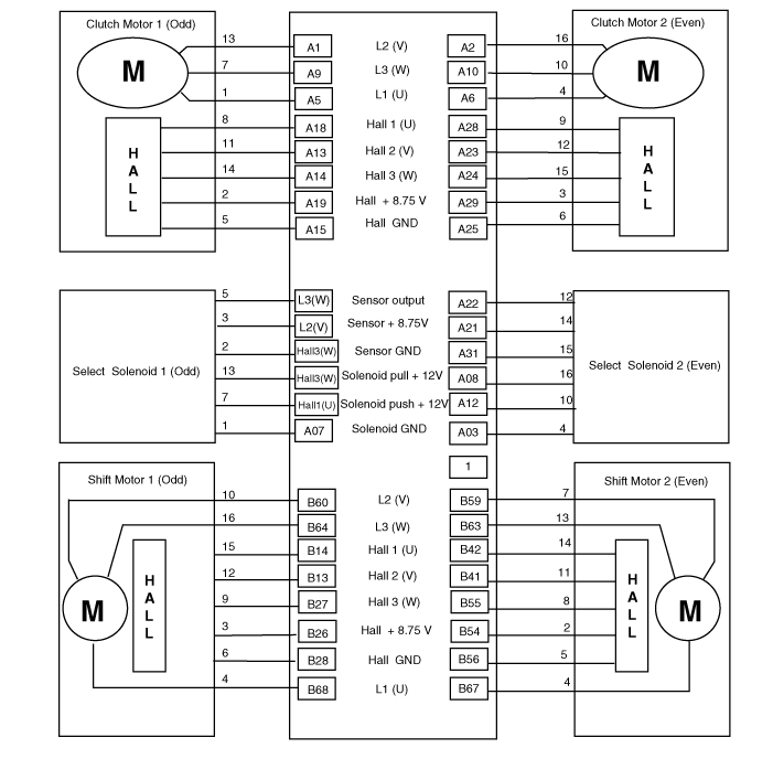
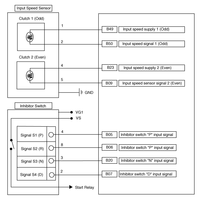
Wiring Diagram
Repair Procedures
Inspection
TCM Ground Circuit Inspection: Measure the resistance between the TCM and chassis ground. Use the rear side of the TCM harness connector as the check point on the TCM side.
Specification: Less than 1 ohm
TCM Connector Inspection: Disconnect the TCM connector and visually inspect the ground terminals on the TCM side and the harness side for bent pins or poor contact pressure.
If the problem is not found in Steps 1 and 2, the TCM may be faulty. Replace the TCM with a new one, then recheck the vehicle. If the vehicle operates normally, the problem was most likely in the TCM.
Retest of Original TCM: Install the original TCM (which may be faulty) in a known good vehicle and check the vehicle. If the problem recurs, replace the original TCM with a new one. If the problem does not occur, it is an intermittent problem. If the problem does not occur, the problem was most likely with other parts.
Removal
Disconnect the negative (-) battery cable.
Remove the Integrated Central Control Unit (ICU).
(Refer to Body Electrical System - "Integrated Central Control Unit (ICU)")
Disconnect the TCM connectors (A).
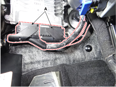
Remove the TCM (A) after loosening the nuts.
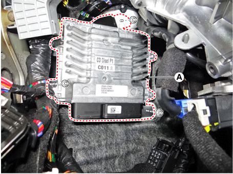
Installation
Install in the reverse order of removal.
Test yourself
A quick Kia Forte BD quiz: every answer comes with an explanation and a link to the manual page.