Inhibitor Switch
Components and Component Location
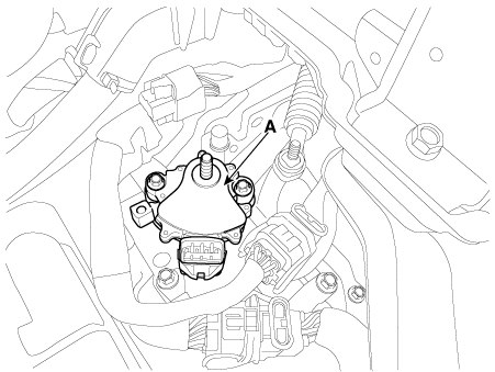
Component Location
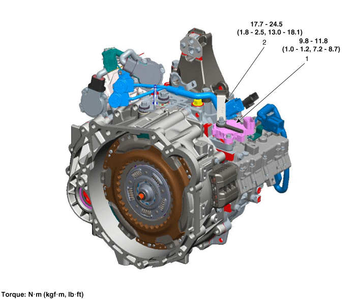
| 1. Inhibitor Switch | 2. Manual Control Lever |
Specifications
Specification
| Item | Specification |
| Power Supply | 12 V |
| Output type | Output signal combination |
Signal Code Table
| P | P-R | R | P-R | N | N-D | D | |
| Signal "1" | 12 V | 12 V | 0 | 0 | 0 | 0 | 0 |
| Signal "2" | 0 | 12 V | 12 V | 12 V | 0 | 0 | 0 |
| Signal "3" | 0 | 0 | 0 | 12 V | 12 V | 12 V | 0 |
| Signal "4" | 0 | 0 | 0 | 0 | 0 | 12 V | 12 V |
Description and Operation
Description
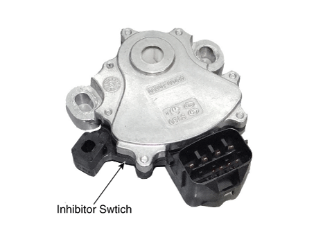
The inhibitor switch is installed on the top of the transmission and is connected to the shift lever through the shift cable.
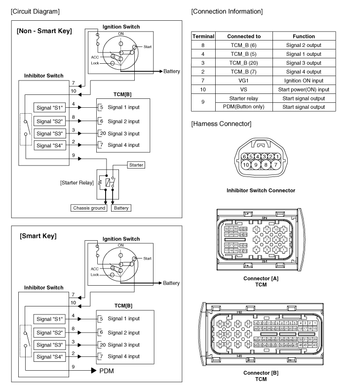
Inhibitor switch signals (S1, S2, S3, S4) are sent to the TCM depending on the driver's shift lever operation.
Circuit Diagrams
Wiring Diagram
Troubleshooting
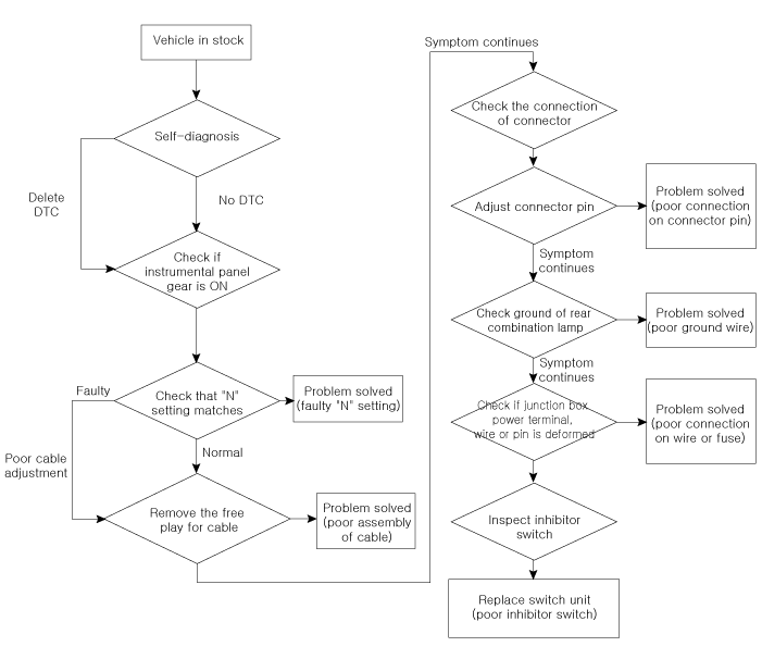
Troubleshooting
Repair Procedures
Inspection
Check the diagnostic trouble codes (DTCs) using the KDS.
Check that the "N" range adjustment is correct.
(Refer to Lock Switch - "Installation")
Check the free play of the shift cable.
(Refer to Shift Cable - "Installation")
Check the condition of the connector.
Carefully inspect the connector for looseness, poor contact, bending, corrosion, contamination, deformation, or damage.
Turn the ignition switch ON and the engine OFF, then measure the supply voltage to the inhibitor switch circuit and the voltage between the terminal and ground.
Specification: approx. 12 V
Check the ground condition of the rear combination lamp circuit.
Check the wiring connection condition of the power terminal of the junction box and the fuse lamp.
Check that the fuse holder is not separated and that the fuse is held firmly.
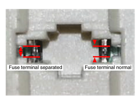
Connect a test fuse to check whether it is connected correctly.
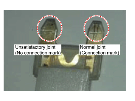
Check whether the fuse is damaged.
Check the signal of the lock switch circuit.
Turn the ignition switch ON and the engine OFF.
Measure the voltage between each signal terminal and chassis ground in each range (P, R, N, D).
Specification: approx. 12 V
Signal Code Table
P P-R R P-R N N-D D Signal "1" 12V 12V 0 0 0 0 0 Signal "2" 0 12V 12V 12V 0 0 0 Signal "3" 0 0 0 12V 12V 12V 0 Signal "4" 0 0 0 0 0 12V 12V
Removal
Move the shift lever to the "N" position.
Remove the air duct and air cleaner assembly.
(Refer to Engine Mechanical System - "Air Cleaner")
Disconnect the shift lock switch connector (A).
Loosen the shift cable mounting nut (B).
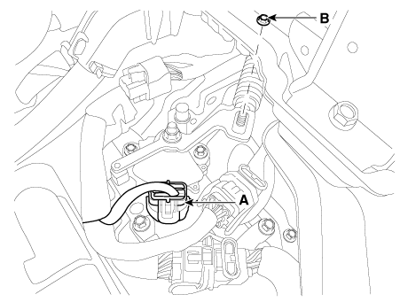
Remove the manual control lever (A).
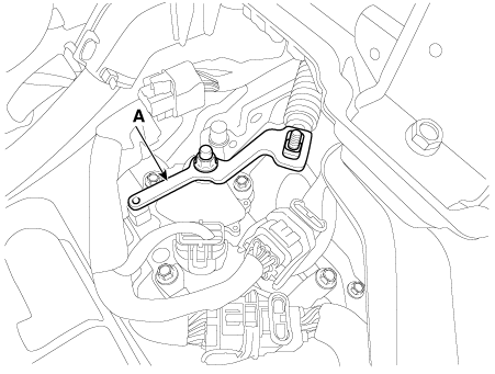
Remove the lock switch (A).
Installation
Make sure the shift lever is in the "N" position.
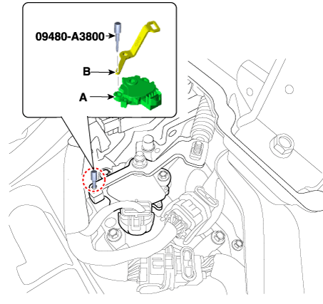
Install the inhibitor switch (A).
Install the manual control lever (A).
Align the hole (B) in the manual control lever with the "N" position hole (A) of the lock switch, then insert the SST guide pin (09480-A3800) into the lock switch.
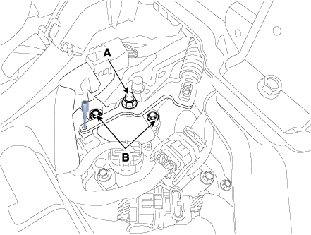
Tighten the manual control lever nut (A) to the specified torque.
Tightening torque: 17.7 - 24 N·m
Tighten the mounting bolts of the lock switch (B) to the specified torque.
Tightening torque: 9.8–11.8 N·m
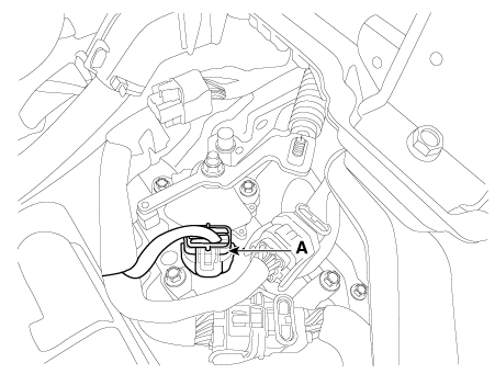
Remove the SST (09480-A3800) from the adjustment hole.
Connect the shift lock switch connector (A).
Loosely tighten the nut (A).
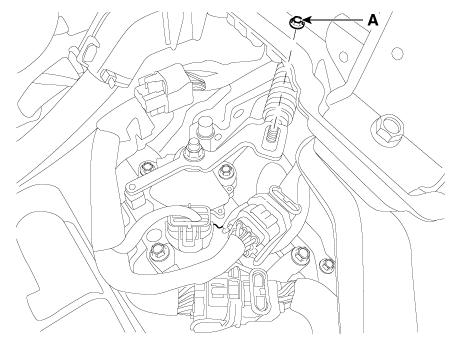
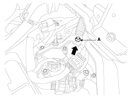
Tighten the nut (A) to the specified torque after eliminating the play, while pressing the shift cable in the direction indicated by the arrow.
Tightening Torque: 9.8–14.7 N·m
Install the air duct and air cleaner assembly.
(Refer to Engine Mechanical System - "Air Cleaner")
Test yourself
A quick Kia Forte BD quiz: every answer comes with an explanation and a link to the manual page.