Gear Shift Actuator Assembly
Components and Component Location
Component Location
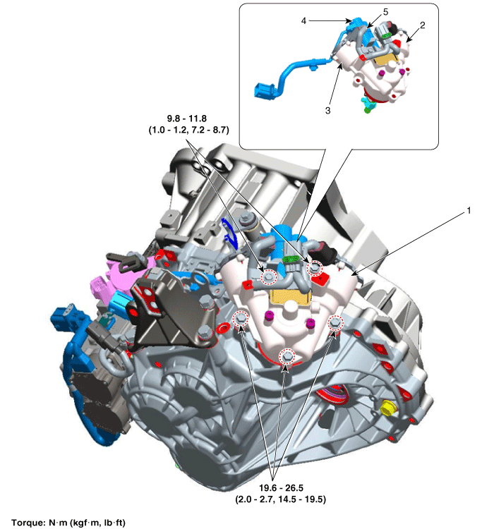
| 1. Gear Shift Actuator Assembly 2. Shift Motor (Even) 3. Shift Motor (Odd) |
4. Select Solenoid (Even) 5. Select Solenoid (Odd) |
Specifications
Specification
| Item | Specification | |
| Resistance (between lines) | Shift Motor 1/2 | 135.4 mΩ ± 10 % |
| Select Solenoid 1/2 | 0.7 mΩ ± 10 % | |
| Max. Current | Shift Motor 1/2 | 45 A |
| Select Solenoid 1/2 | 20 A | |
| Select Solenoid Sensor Output | Push | 4.0 ± 0.15 V |
| Pull | 1.0 ± 0.15 V | |
| Operating Condition | -40 to 257 °F (-40 to 125 °C) | |
| Rated Voltage | 13 V | |
| Sensor Supply Voltage | 8.75 V ± 10% | |
Description and Operation
Description
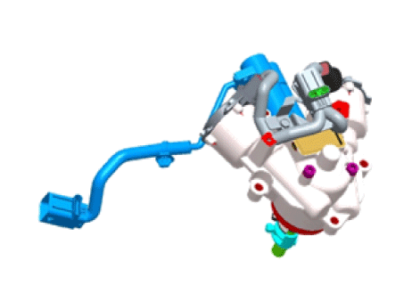
The gear shift actuator consists of a shift motor and a select solenoid.
The shift motor and select solenoid of the gear shift actuator are controlled by signals from the TCM to operate the gear.
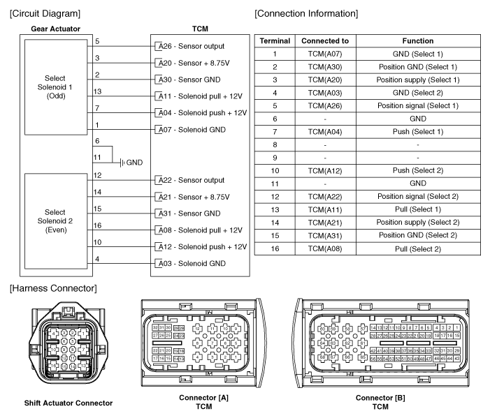
Circuit Diagrams
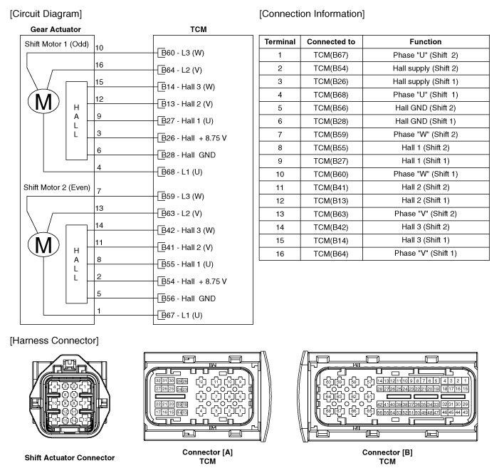
Wiring Diagram
Repair Procedures
Removal
Move the shift lever to the "N" position.
Remove the air cleaner assembly and air duct.
(Refer to Engine Mechanical System - "Air Cleaner")
Remove the battery and battery tray.
(Refer to Engine Electrical System - Battery)
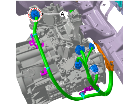
Disconnect the gear actuator motor connector (A).
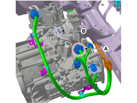
Remove the wiring harness clamp (B) after disconnecting the gear shift actuator solenoid connector (A).
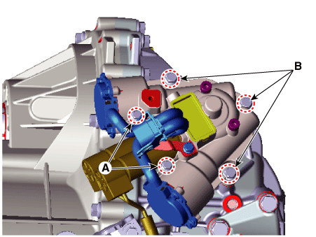
Remove the gear shift actuator assembly after loosening the bolts (A, B).
Tightening torque:
(A) 9,8–11.8 N·m
(B) 19,6–26 N·m
Installation
Install in the reverse order of removal.
Test yourself
A quick Kia Forte BD quiz: every answer comes with an explanation and a link to the manual page.