Clutch Actuator Assembly
Components and Component Location
Component Location
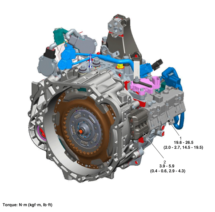
| 1. Clutch Actuator Assembly | 2. Fork Cover |
Specifications
Specification
| Item | Condition | Specification |
| Resistance (between lines) | Motor 1 | 60 mΩ ±10 % |
| Motor 2 | 64 mOhm ± 10% | |
| Rated Voltage | 12 V | |
| Operating Condition | -40 to 257 °F (-40 to 125 °C) | |
Description and Operation
Description
The clutch actuator uses signals from the Transmission Control Module (TCM) to control the clutch.
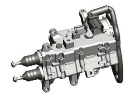
Circuit Diagrams
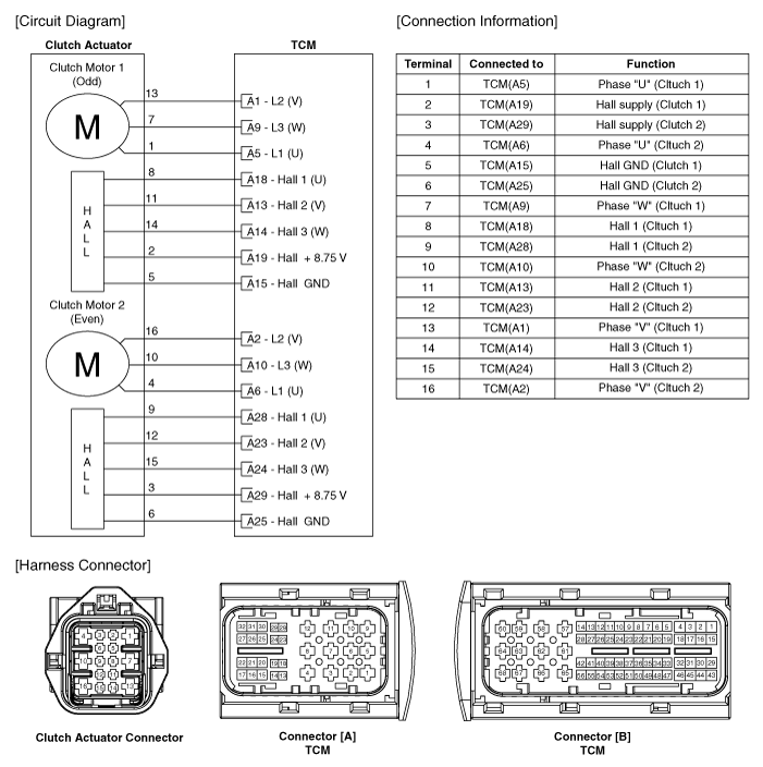
Wiring Diagram
Video Clip


Removal
Remove the air cleaner assembly and air duct.
(Refer to Engine Mechanical System - "Air Cleaner")
Remove the battery and battery tray.
(Refer to Engine Electrical System - Battery)
Remove the lock switch.
(Refer to Dual Clutch Transmission Control System - "Inhibitor Switch").
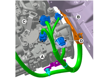
Disconnect the connectors (A, B, C, D) shown in the illustration below.
A. Inhibitor Switch Connector
B. Input Shaft Speed Sensor Connector
C. Gear Actuator Solenoid Connector
D. Clutch Actuator Connector
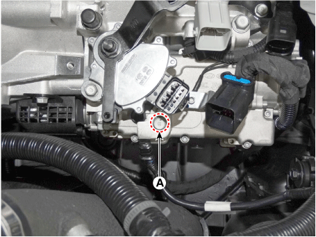
Loosen the ground bolt (A).
Tightening Torque: 9.8–11.8 N·m
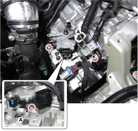
Loosen the clutch actuator mounting bolts (A).
Tightening torque: 19.6–26 N·m
Remove the under cover.
(Refer to Engine Mechanical System - "Engine Room Cover")
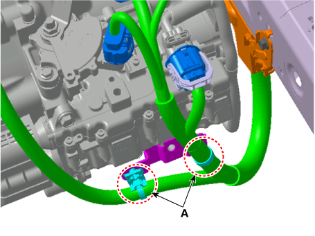
Remove the wire harness bracket mounting clips (A).
Remove the vacuum pump.
(Refer to Brake System - "Vacuum Pump")
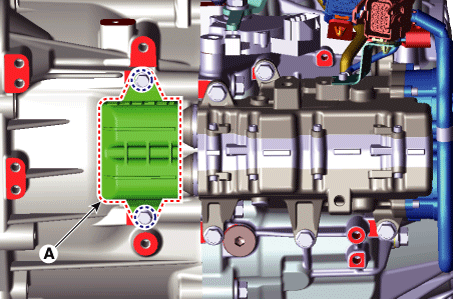
Remove the fork cover (A).
Tightening torque: 3.9 ~ 5.9 N·m
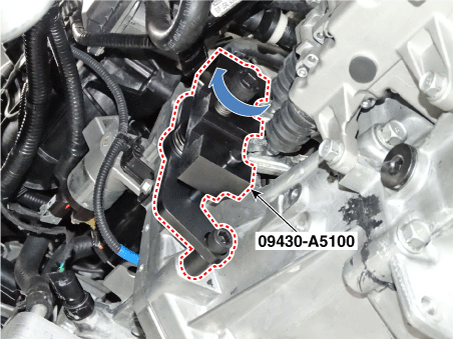
Install the Special Service Tool (09430-A5100).
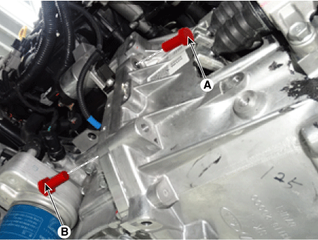
Loosen the starter mounting bolt (A) and the transmission mounting bolt (B).
Tightening torque:
(A) 49,0–64 N·m
(B) 42,2–54 N·m
Secure the clutch fork by installing the Special Service Tool (09430-A5100).
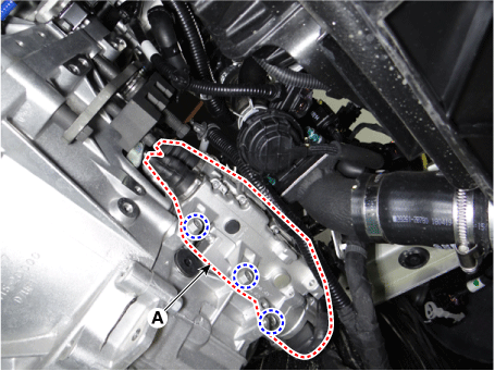
Remove the clutch actuator unit (A) after loosening the bolts.
Tightening torque: 19.6–26 N·m
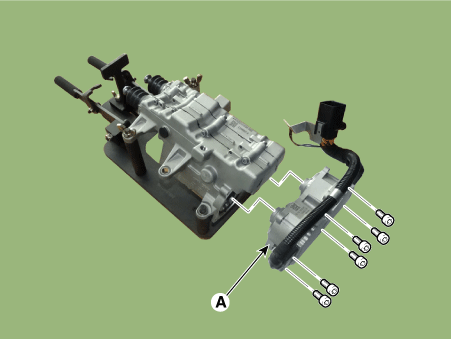
Remove the clutch actuator motor (A), if necessary.
Installation
Install in the reverse order of removal.
Adjustment
(Refer to Video Clip)
A. Rod Length Rewinding (When Replacing Only the Clutch Actuator)
Remove the clutch actuator.
(Refer to Clutch Actuator Assembly - "Removal")
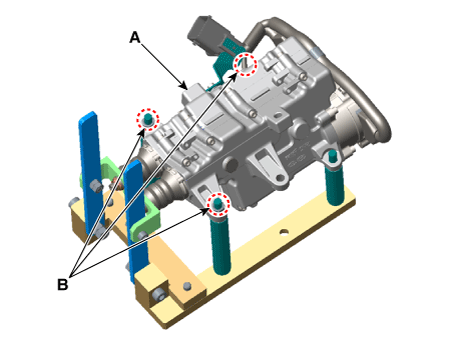
Secure the clutch actuator (A) removed from the vehicle with the nut (B) after installing it on the SST (09430-C1302).
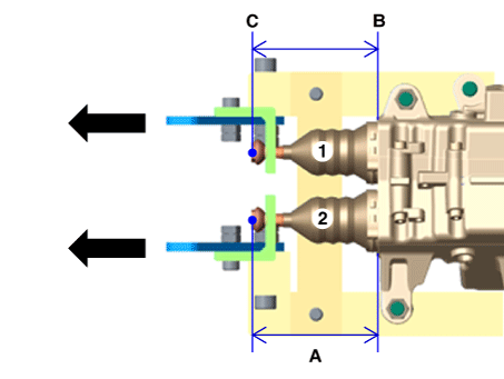
Measure and record the length of the old rod in the state of pulling the clutch actuator lever.
Length of old rod (A): Length from the base surface (C) to the rod end (B).
Clutch Actuator Rod 1
Clutch Actuator Rod 2
Remove the clutch actuator from the SST (09430-C1302).
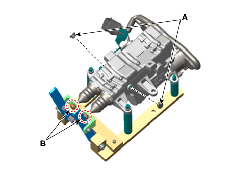
Secure with the nut (B) after installing the new clutch actuator (A) on the SST (09430-C1302).
Secure the rod to the hook (B) after removing the rubber seal (A).
Record each length of the new rod (A) after measuring it while pulling the new clutch actuator lever.
Length of new rod (A): Length from the base surface (C) to the rod end (B).
Clutch Actuator Rod 1
Clutch Actuator Rod 2
Install the clutch actuator vertically, which is installed using the SST (09430-C1302).
Remove the clutch actuator hook (A) from the SST lever.
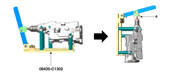
Press the end of the rod (A) and release the pressure when you see the nut protrusion (B).
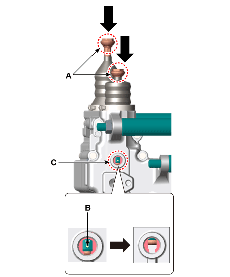
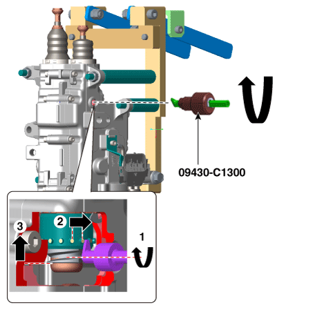
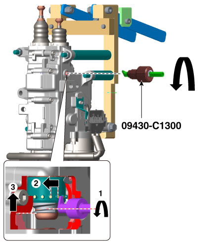
Insert the SST (09430-C1300) into the hole of the seal rubber.
Adjust the length of the new clutch actuator rod by turning the SST counterclockwise to match the "old rod length" measured in step 3.
Increase rod length (+): Counterclockwise rotation / 1 turn (+0.25 mm / +0.009 in)
Decrease rod length (-): Clockwise rotation / 1 turn (-0.25 mm / -0.009 in)
Place the clutch actuator horizontally with the SST (09430-C1302) installed.
Insert the clutch actuator hook (A) into the SST lever.
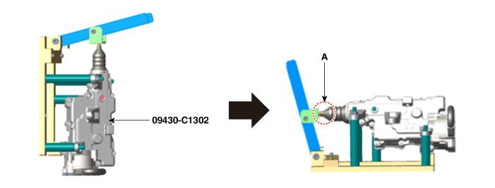
Check that the "clutch actuator rod length" obtained by the adjustment and the "old clutch actuator rod length" measured in step 3 are the same when the clutch lever is pulled.
Rod length (A): Length from the base surface (C) to the end of the rod (B).
Clutch Actuator Rod 1
Clutch Actuator Rod 2
Install the seal rubber (A).
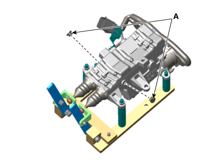
Remove the clutch actuator from the SST (09430-C1302).
Remove the clutch actuator.
(Refer to Clutch Actuator Assembly - "Removal")
Secure the clutch actuator (A) removed from the vehicle with the nut (B) after installing it on the SST (09430-C1302).
Secure the rod to the hook after removing the seal cap (A).
An initialization procedure is required if the measured rod length of the clutch actuator removed from the vehicle, measured with the clutch lever pulled, is shorter than the initial length specification.
Rod length (A): Length from the base surface (C) to the end of the rod (B).
(Initial length: 71.5 - 72.5 mm / 2.81 - 2.85 in.)
Clutch Actuator Rod 1
Clutch Actuator Rod 2
Place the clutch actuator vertically with the SST (09430-C1302) installed.
Remove the clutch actuator hook (A) from the SST lever.
Press the end of the rod (A) and release the pressure when you see the nut protrusion (B).
Insert the SST (09302-C1300) into the hole of the seal rubber.
Adjust the clutch actuator rod length by turning the SST counterclockwise.
Increase rod length (+): Counterclockwise rotation / 1 turn (+0.25 mm / +0.009 in)
Decrease rod length (-): Clockwise rotation / 1 turn (-0.25 mm / -0.009 in)
Place the clutch actuator horizontally with the SST (09430-C1302) installed.
Insert the clutch actuator hook (A) into the SST lever.
Check that the "clutch actuator rod length" obtained by the adjustment and the "clutch actuator initialization rod length" are the same when the clutch lever is pulled.
Rod length (A): Length from the base surface (C) to the end of the rod (B).
(Initial length: 71.5 - 72.5 mm / 2.81 - 2.85 in.)
Clutch Actuator Rod 1
Clutch Actuator Rod 2
Install the seal rubber (A).
Remove the clutch actuator from the SST (09430-C1302).
Test yourself
A quick Kia Forte BD quiz: every answer comes with an explanation and a link to the manual page.