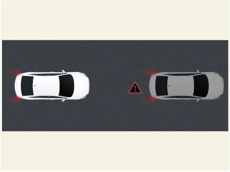
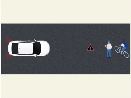
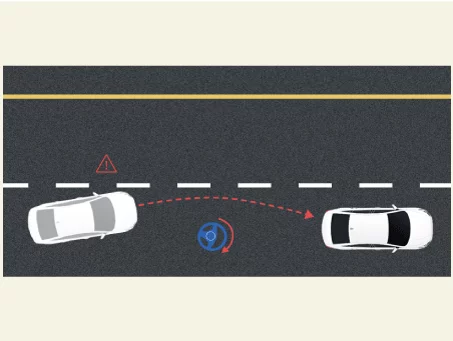
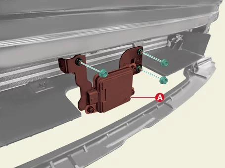
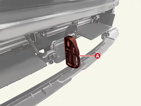
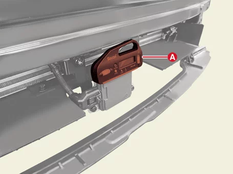
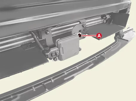
Forward Collision - Avoidance Assist (FCA) : This function may help automatically bring the vehicle to a stop or with avoidance steering if the preceding vehicle suddenly slows down, or if a forward collision risk is detected, such as a stopped vehicle, a pedestrian, or a cyclist in front.
Basic Function : If the preceding vehicle suddenly slows down, or if a forward collision risk is detected, such as a stopped vehicle, a pedestrian, or a cyclist in front, FCA provides a warning. After the warning, if the risk of collision increases, FCA automatically assists with emergency braking.
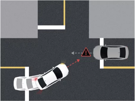
Forward Collision - Avoidance Assist - Junction Turning (FCA - JT) : Warns if the left turn signal switch is activated at an intersection and the risk of collision with an oncoming vehicle from an adjacent lane is detected while turning left. Automatically assists with braking if the risk of collision increases after warning.
Lane Keeping Assist (LKA) : Warns if a lane departure is detected without a turn signal switch on. Automatically assists steering to prevent the vehicle from departing the lane only if lane departure is detected without a turn signal switch on.
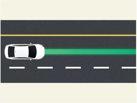
Lane Following Assist (LFA) : Recognizes the lane ahead keeping the vehicle in the center of the lane.
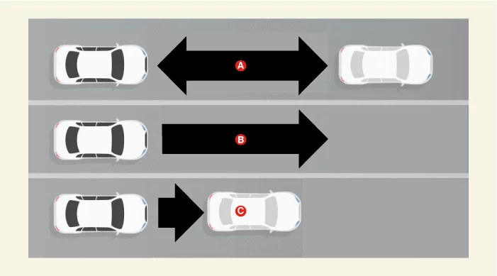
Smart Cruise Control with Stop & Go (SCC w/S&G) : SCC helps maintain distance from the vehicle ahead and drive at a speed set by the driver. It also automatically stops when the car in front stops and automatically starts when the car in front departs. If a period of time has elapsed, start again by pressing the accelerator pedal or operating the + / - switch.
A : keeps at a certain distance. (Driving at the speed of the vehicle ahead)
B : Constant speed drive at set speed.
C : Automatic deceleration.
Navigation - based Smart Cruise Control (NSCC) : NSCC helps drive at a safe speed on the highway using navigation. If the driver sets the set speed to the current speed limit on the highway during NSCC operation, the set speed changes automatically whenever the speed limit changes.
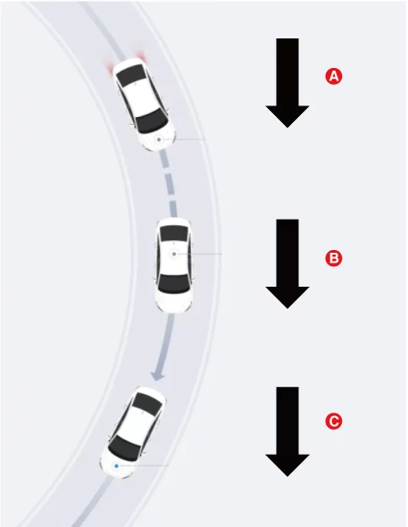
Navigation - based Smart Cruise Control - Curve Zone (NSCC-C) : In a highway curved section, the speed is automatically reduced appropriately before entering the curve. When leaving the curve, the speed is returned to the previous setting.
A : Setting Speed
B : Deceleration at safe speed
C : Acceleration at set speed
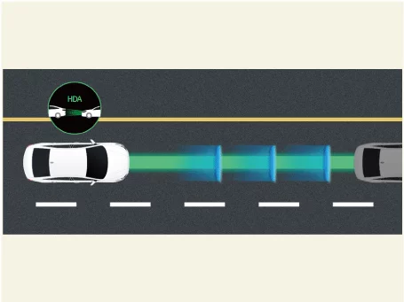
Highway Driving Assist (HDA) : HDA helps maintain a set distance and speed from the vehicle ahead when driving on a highway and helps center the vehicle in the lane while driving, even through a curve.
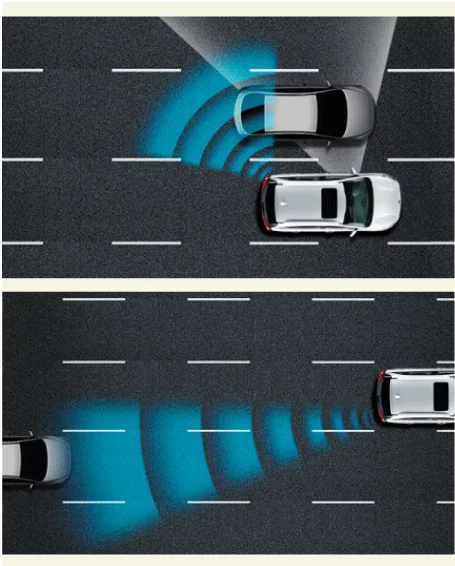
Blind-Spot Collision Warning (BCW) : It detects blind spots and rear high-speed approach vehicles when driving and warns drivers.
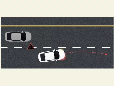
Blind-Spot Collision - Avoidance Assist (BCA) : When operating the turn signal switch to change lanes, if there is a risk of collision with a rear side vehicle, BCA provides a warning. After the warning, if the risk of collision increases, BCA automatically controls the vehicle to help avoid a collision.
BCA (Driving) : When operating the turn signal switch to change lanes, if there is a risk of collision with a rear side vehicle, BCA provides a warning. After the warning, if the risk of collision increases, BCA automatically controls the vehicle to help avoid a collision.
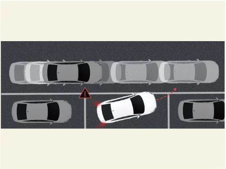
Exiting a parallel parking : If exiting a parallel parking spot and there is a risk of collision with a rear side vehicle, BCA automatically assists with emergency braking.
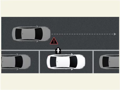
Safe Exit Warning (SEW) : When a vehicle approaching from the rear is detected after stopping the vehicle and the door of the vehicle is opened, it warns the driver with a crash warning phrase and a warning sound on the instrument panel.
Safe Exit Assist (SEA) : When the occupant opens the door to exit the vehicle after a stop, if an approaching vehicle from the rear side is detected, SEA provides a warning. SEA also helps keep the rear door closed through operation of the electronic child lock.
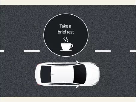
Driver Attention Warning (DAW) : DAW displays the driver’s attention level while driving. Provides a warning when signs of driver inattentiveness are detected, and recommends a rest if needed.
Leading Vehicle Departure Alert (LVDA) : It notifies you when the vehicle ahead departs while at a stop or traffic light.
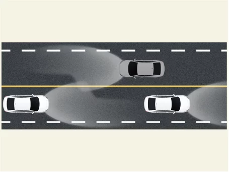
High Beam Assist (HBA) : HBA recognizes the ambient light and illuminance, such as the lamp of an opposite vehicle or preceding vehicle, and automatically turns the high beam On/Off.
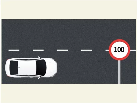
Intelligent Speed Limit Assist (ISLA) : ISLA warns if driving over the speed limit of the road using the information of the front view camera or navigation. Set speed can be changed according to the speed limit during MSLA or SCC operation.
Components and Components Location
Component
[Front]
[Rear]
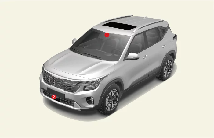
1. Front View Camera 2. Front Radar
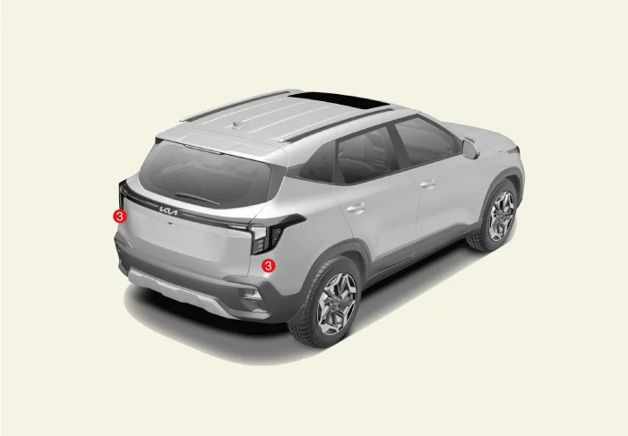
3. Rear Corner Radar
Rear Corner Radar Specification
Specification
Item
Specification
Rated voltage (V)
11.5 - 12.5
Operating voltage (V)
9 - 16
Quantity
2
Max. distance [m (ft.)]
70 (229.66)
Rear Corner Radar On Vehicle Inspection
On Vehicle Inspection
Visual Inspection If there is a problem with BCW / BCA / SEA / RCCW / RCCA, check the items below.
Checking bumper cleanliness: If the bumper is contaminated with snow or dust, performance will be reduced.
Check the condition around the bumper : Warning lights may occur if metal stickers or foreign substances are attached to the radar.
Checking bumper geometry or mounting status : Warning lights may occur if bumper or radar is not properly installed after an accident.
Check the operation status of the switch: Press the switch to check whether the LED works.
The advanced driver assistance system (driving) can be more quickly diagnosed for problems with the KDS. (Refer to "DTC guide")
Self diagnosis : Inspect the Diagnostic Trouble Code (DTC) with the KDS. (Refer to DTC guide when fault code is found.)
S/W Management : Controlling other features including system option setting and zero point adjustment. (S/W Management → Rear Corner Radar → Variant Coding) (S/W Management → Rear Corner Radar → BCW(BSD) Radar Calibration)
Refer to the KDS screen for operating conditions and details.
Check the bumper, bracket, or radar when a diagnostic trouble code occurs.
If the rear corner radar is damaged, replace only therear corner radar.
Remove the rear bumper assembly. (Refer to Body - "Rear Bumper Assembly")
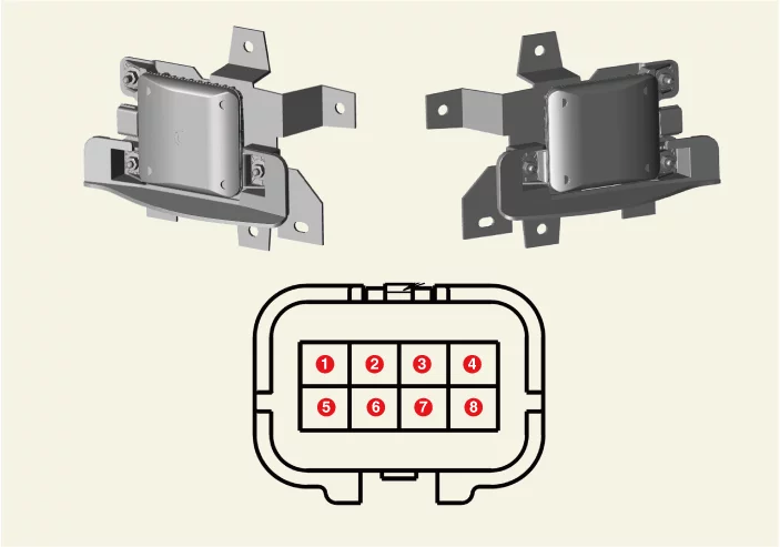
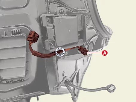
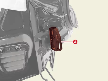
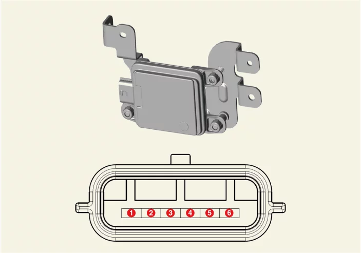
Disconnect the rear corner radar connector (A).
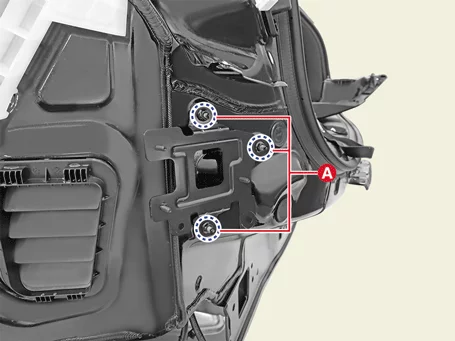
Remove the rear corner radar (A) after removing the nuts.
Tightening torque : 8.8 - 10,8 N·m
The rear corner radar will not operate normally if the bracket or radar is damaged.
Extension Wiring
If the extension wiring or connector is damaged, replace only the extension wiring.
Remove the rear bumper assembly. (Refer to Body - "Rear Bumper Assembly")
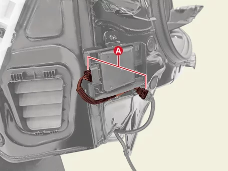
Disconnect the extension wiring connector (A).
Remove the extension wiring (A) after removing the clip.
Clip position :
Rear Corner Radar Bracket
If the rear corner radar bracket is damaged, replace only the rear corner radar bracket.
Remove the rear corner radar. (Refer to Rear Corner Radar - "Removal")
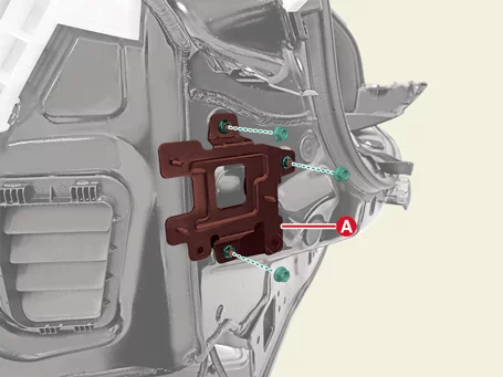
Remove the rear corner radar bracket (A) after removing the nuts.
Tightening torque : 8.8 - 10,8 N·m
The rear corner radar will not operate normally if the bracket or radar is damaged.
BCW & RCCW indicator
Disconnect the battery negative ( - ) terminal.
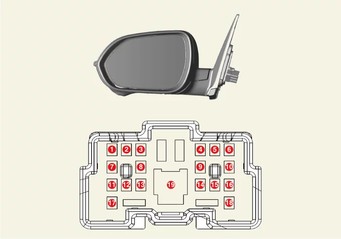
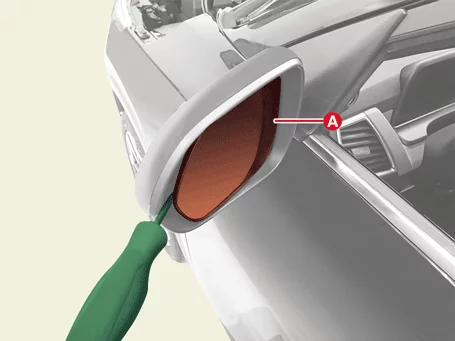
Remove the mirror (A) by applying slight force, after inserting a remover as shown below.
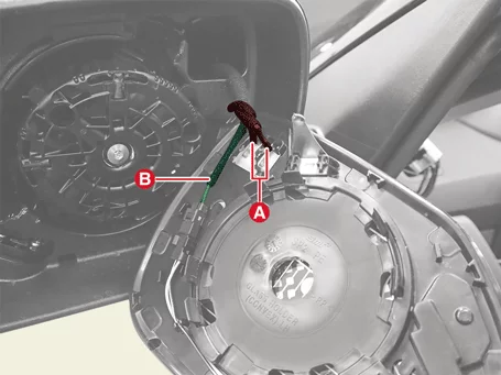
Disconnect the mirror heater connectors (A) and BCW & RCCW indicator connector (B).
Rear Corner Radar Installation
Installation
Rear Corner Radar
Install in reverse order of removal.
1) Parts number 2)RL (Rear - Left side), RR (Rear - Right side)
Perform the order below with the KDS when replacing the rear corner radar unit. (S/W Management → Rear Corner Radar → Variant Coding)
Refer to the KDS screen for operating conditions and details.
Perform the rear corner radar mounting angle calibration procedure. (Refer to Rear Corner Radar - "Adjustment")
Install in reverse order of removal.
BCW & RCCW indicator
Rear Corner Radar Adjustment
Adjustment
Rear Corner Radar Calibration Inspection
Check the rear corner radar mounting angle when replacing the bracket or any components of rear corner radar.
Check the rear corner radar mounting angle when a vehicle equipped with the rear corner radar system has a rear or side collision.
Check Before Rear Corner Radar Calibration
When a failure code [C270854], [C270954] occurs, check the following before performing calibration.
Check the vehicle condition and whether the rear corner radar unit or bracket is deformed (mounting angle, twisted vehicle body, etc.).
Vehicle Check
Normal
Abnormal (deformation of the bracket or bolted area)
Vehicle Check
Normal
Abnormal (deformation of the bracket or bolted area)
Check the nut tightening and if there is any foreign substance.
Vehicle Check
Normal
Abnormal (deformation of the bracket or bolted area)
Special Service Tool
Tool Name / Number
Illustration
Description
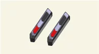
Rear Corner Radar Correction Tool Set 09958 - 3T500
Used to correct the rear corner radar unit.
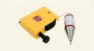
Vertical Plumb 09958 - 3T010
Used to correct the rear corner radar unit. Used to create a center line.
Spirit Level 09958 - 3T070
Used to measure the rear corner radar horizontal angle.
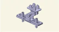
Rear Corner Radar Fixing Adaptor 09958 - 3T080
Used to measure the horizontal angle.
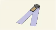
Digital Protractor 09958 - 3T090
Used to measure the horizontal angle.
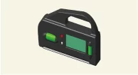
Digital Inclinometer 09958 - 3T100
Used to correct the rear radar unit. Used to measure the vertical angle.
Rear Corner Radar Calibration
Check the items below before performing the rear corner radar calibration.
Park the vehicle on flat ground.
Check that the radar surface is clean.
Check the suspension for damage.
Check the tire alignment.
Check the tire pressure.
Remove the rear bumper assembly. (Refer to Body - "Rear Bumper Assembly")
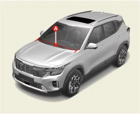
Mark the center point (A) after measuring the distance on top of the hood assembly.
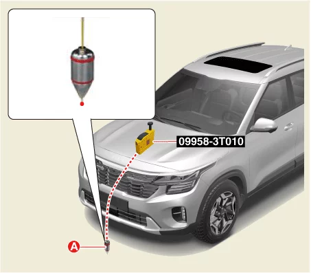
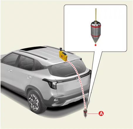
Attach a vertical plumb (09958 - 3T010) on the roof panel, and lower the plumb (A) to the ground so that it passes through the center of the emblem.
Mark the center point below the plumb (A).
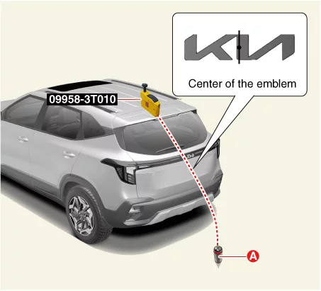
Attach a vertical plumb (09958 - 3T010) on the roof panel, and lower the plumb (A) to the ground so that it passes through the center of the emblem.
Mark the center point below the plumb (A).
Making the center line of the vehicle using a string.
Pass the string through the bottom of the vehicle from the rear of the vehicle to the front and fix the string to the center point (A) of the front of the vehicle.
Fix the string to the point (C) about 1.5 - 2 m (4.95 - 6.6 ft) from the back of the vehicle so that it passes the rear center point (B).
Remove the rear corner radar. (Refer to Rear Corner Radar - "Removal")
Refit the rear corner radar unit fixing adapter (special tool: 09958 - 3T080) to the rear radar unit and secure the horizontal laser (special tool: 09958 - 3T070).
Measure the angle (C) between the center line (A) of the angle measuring and the horizontal laser beam (B) using a digital protractor (09958 - 3T090).
Horizontal angle : 57°
Measure the vertical angle of the rear radar unit using a digital horizontal system (special tool: 09958 - 3T100).
Vertical angle : 93°
Make sure to perform the zero setting horizontally before using a digital inclinometer.
Note that depending on the display method of the digital inclinometer, the ( + ) / ( - ) angle may be displayed differently.
If the measured values deviate from the specified values, insert a washer (A) between the bracket of the rear corner radar unit.
install the rear corner radar. (Refer to Rear Corner Radar - "Removal")
Install the rear bumper assembly. (Refer to Body - "Rear Bumper Assembly")
Check that the rear corner radar is clean before installing the rear bumper assembly.
Perform the order below with the KDS. (S/W Management → Rear Corner Radar → BCW(BSD) Radar Calibration)
Refer to the KDS screen for operating conditions and details.
Front Radar Specification
Specification
Item
Specification
Rated voltage (V)
11.5 - 12.5
Operating voltage (V)
9 - 16
Mounting angle (°)
Horizontal
-0.8 to 0.8
Vertical
-0.4 to 0.4
Front Radar On Vehicle Inspection
On Vehicle Inspection
Visual inspection If there is a problem with the front radar check the items below.
Checking bumper cleanliness : If the bumper is contaminated with snow or dust, may be disable during operation.
Check the condition around the bumper : Warning lights may occur if metal stickers or foreign substances are attached to the radar.
Checking bumper geometry or mounting status : Warning lights may occur if bumper or radar is not properly installed after an accident.
The advanced driver assistance system (driving) can be more quickly diagnosed for problems with the KDS. (Refer to "DTC guide")
Self diagnosis : Inspect the Diagnostic Trouble Code (DTC) with the KDS. (Refer to DTC guide when fault code is found.)
S/W Management : Controlling other features including system option setting and zero point adjustment. (S/W Management → Front Radar → Inspection/correction of the front - radar mounting angle → C1 (Stop mode) (S/W Management → Front Radar → Inspection/correction of the front - radar mounting angle → C2 (Driving mode))
Refer to the KDS screen for operating conditions and details.
Check the bumper, bracket, or radar when a diagnostic trouble code occurs.
The advanced driver assistance system (driving) can be more quickly diagnosed for problems with the KDS. (Refer to "DTC guide")
Self diagnosis : Inspect the Diagnostic Trouble Code (DTC) with the KDS. (Refer to DTC guide when fault code is found.)
S/W Management : Controlling other features including system option setting and zero point adjustment. (S/WManagement → Front View Camera → System Identification) (S/W Management → Front View Camera → Variant Coding) (S/W Management → Front View Camera → SPTAC Calibration)
Refer to the KDS screen for operating conditions and details.
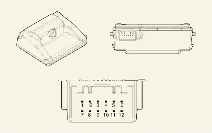
Front View Camera Connector And Terminal Function
Connector And Terminal Function
Pin No
Connector
1
-
2
-
3
L-CAN (Low)
4
C-CAN (Low)
5
-
6
-
7
IG
8
-
9
L-CAN (High)
10
C-CAN (High)
11
Ground ( - )
12
-
Front View Camera Removal
Removal
Perform the order below with the KDS before replacing the front view camera. (S/W Management → Front View Camera → System Identification)
Refer to the KDS screen for operating conditions and details.
Disconnect the battery negative ( - ) terminal.
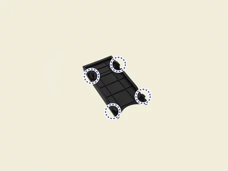
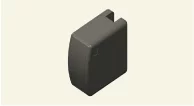
Remove the multi sensor blanking cover (A).
Clip position :
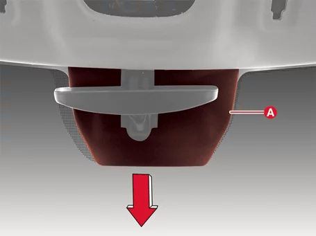
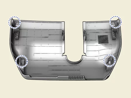
Remove the multi sensor cover (A) in the direction of the arrow.
Clip position :
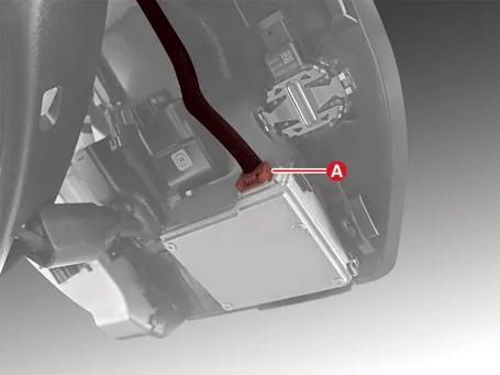
Disconnect the front view camera connector (A).
Remove the front view camera (A) by pulling both hooks.
Clip position :
Front View Camera Installation
Installation
Install in reverse order of removal.
Check that the front view camera mounting area (windshield glass) is clean before installing the front view camera.
Perform the order below with the KDS when replacing the front view camera unit. (S/W Management → Front View Camera → Variant Coding)
Refer to the KDS screen for operating conditions and details.
Enter the specification value read from the existing camera into the new front view camera.
Perform the front view camera unit calibration. (Refer to Front View Camera - "Adjustment")
Front View Camera Adjustment
Special Service Tool
Tool Name / Number
Illustration
Description
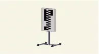
Front View Camera Calibration target 09890 - 3V100
Used for compensating front view camera unit
SCC Setting Beam 09964 - C1200
Used for front radar unit setting. Used for front view camera unit setting.
Front View Camera Calibration
Perform the front view camera calibration in the following cases.
When the front view camera is reinstallation.
When the front view camera bracket is deformed.
When the front view camera is replaced.
When the windshield glass is replaced.
When the DTC occurs for the front view camera.
Check the items below before performing the front view camera calibration.
Park the vehicle on flat ground.
Check that the windshield glass is clean.
Check the suspension for damage.
Check the tire alignment.
Check the tire pressure.
Front View Camera Service Point Target Auto Calibration (SPTAC)
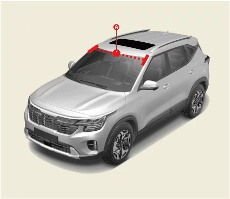
Mark the center point (A) after measuring the distance on top of the windshield glass.
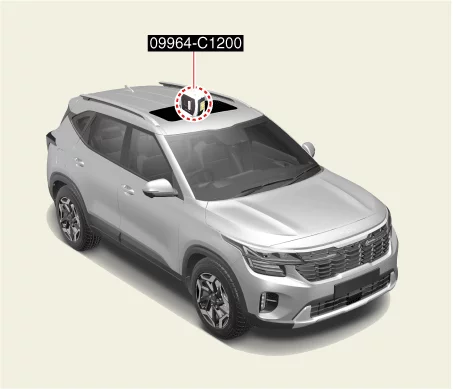
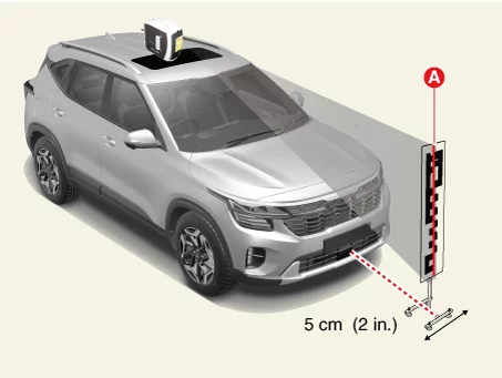
Install the SCC setting beam (09964 - C1200) in the center of the roof above the windshield glass of the vehicle (same for both short and long distance calibrations).
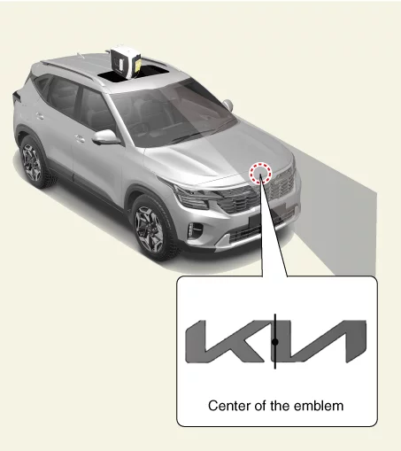
Allow the beam of the SCC setting beam (09964 - C1200) to pass through the center of the emblem.
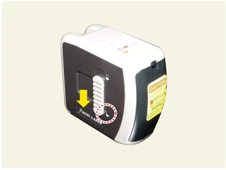
The level laser must be set to 'ON' and the holding (locking) function is not used.
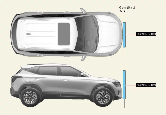
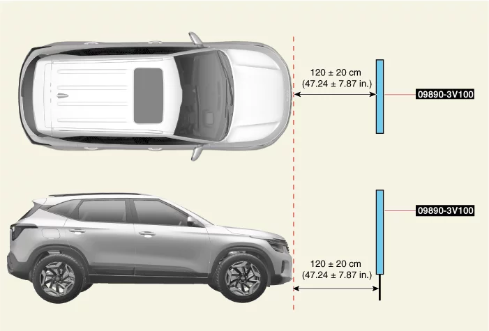
The height of the front view camera calibration target (09890 - 3V100) is adjusted to be 90 ± 2 cm (36 ± 0.8 in.) from the ground.
Place the front view camera calibration target (09890 - 3V100) so that it maintains a distance of 0 cm (0 in.) from the bumper. [Maximum tolerance : 10 cm (4 in.)]
Install the front view camera calibration target (09890 - 3V100) center (A) in line with the laser vertical line of the SCC setting beam (09964 - C1200). [Maximum tolerance: 5cm (2 in)]
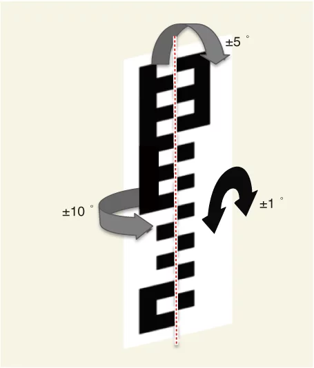
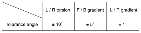
Align the front view camera calibration target (09890 - 3V100) referring to the tolerance angle below.
Tolerance is important and sensitive to floor conditions.
Perform the order below with the KDS. (S/W Management → Front View Camera → SPTAC Calibration)
Refer to the KDS screen for operating conditions and details.
The height of the front view camera calibration target (09890 - 3V100) is adjusted to be 90 ± 2 cm (36 ± 0.8 in.) from the ground.
Place the front view camera calibration target (09890 - 3V100) so that it maintains a distance of 120 cm (48 in.) from the bumper. (Maximum tolerance : 20 cm (8 in.))
Install the front view camera calibration target (09890 - 3V100) center (A) in line with the laser vertical line of the SCC setting beam (09964 - C1200). [Maximum tolerance: 5cm (2 in)]
Align the front view camera calibration target (09890 - 3V100) referring to the tolerance angle below.
Tolerance is important and sensitive to floor conditions.
Perform the order below with the KDS. (S/W Management → Front View Camera → SPTAC Calibration)
Refer to the KDS screen for operating conditions and details.
Check the DTC and warning lamp after erasing the DTC with the KDS.
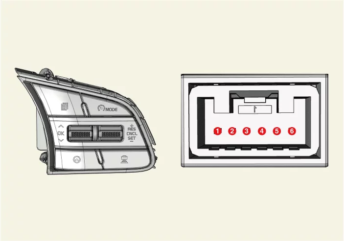
Driver Driving Assistance Switch Connector And Terminal Function
Connector And Terminal Function
Pin No
Connector
1
Trip switch 1 input ( + )
2
Trip switch 2 input ( + )
3
ILL ( + )
4
-
5
ILL ( - )
6
Trip switch input ( - )
Driver Driving Assistance Switch Removal and Installation
Removal
Driver Driving Assistance Switch
Remove the steering wheel remote controller. [RH] (Refer to Body Electrical System - "Steering Wheel Remote Controller (SWRC)")