Align the steering wheel in a straight-ahead position using a digital level or other equivalent tools.
Allowable steering wheel alignment range : 0.0 ± 0.5°
Fix the steering wheel by using a tool such as a steering wheel holder.
Changing the clockspring neutral position by rotating the steering wheel with the steering column universal joint removed may result in an open circuit and faulty folding of the cable inside the clockspring after installation.
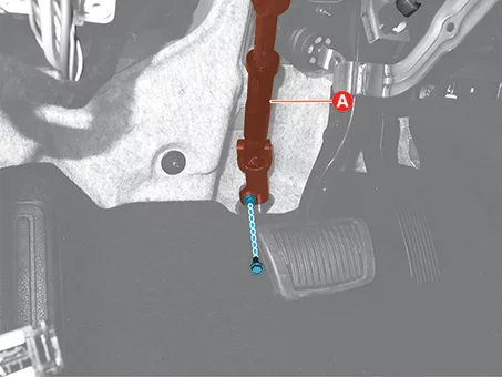
Remove the bolt, and then separate the universal joint (A) from the steering gear box.
Tightening torque : 49.0 - 59 N·m
Do not reuse the universal joint assembly bolt.
Remove the front wheel and tires. (Refer to Tires/Wheels - "Wheel")
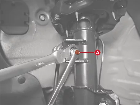
Separate the stabilizer bar link from the front strut assembly after removing the nut (A).
Tightening torque : 98.1 - 118 N·m
Fix the outer stud (A) using a tool such as a wrench when installing and removing the stabilizer bar link nut.
Be careful not to damage the boot of the link.
Use only a hand tool when removing or installing the stabilizer bar link nut.
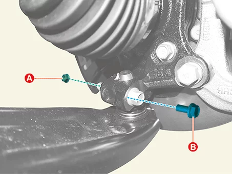
Separate the lower arm ball joint from the front axle.
Remove the lower arm nut (A) and bolt (B).
Tightening torque : 58.8 - 71 N·m
Fix the lower arm ball joint bolt when removing or installing the nut.
Do not reuse the split pin.
Be careful not to change the bolt, nut and washer installing position.
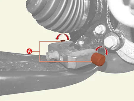
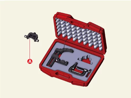
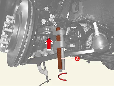
Install the support bolt to the lower arm ball joint mounting hole, and then rotate the bolts (A).
Use the support bolt (A) of the SST (0K545 - A9100).
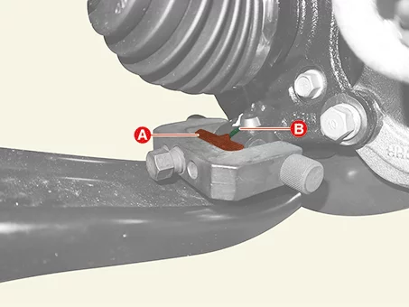
Place the support body (A) between the lower arm and the front axle (B).
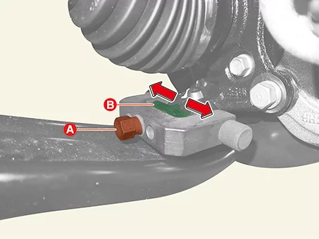
Rotate the bolt (A) clockwise, and then insert the support body (B) to broaden the gap.
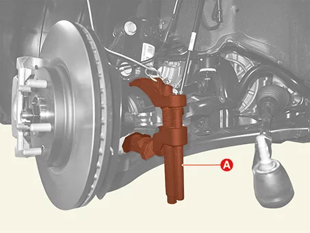
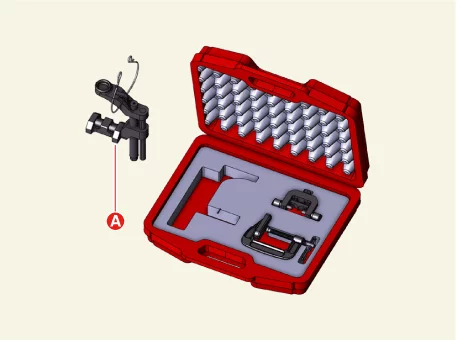
Install the main body (A) between the front strut assembly and front lower arm.
Use the main body (A) of the SST (0K545 - A9100).
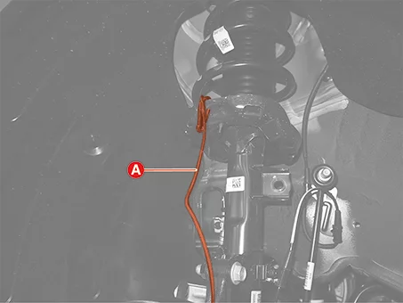
Secure the main body with the wire (A) to prevent it from falling.
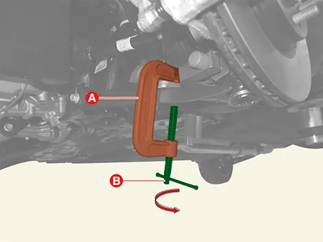
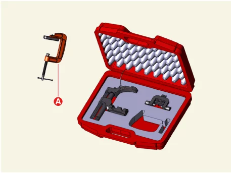
Install the C-clamp (A) by turning the handle (B) to prevent the main body from slipping.
Use the C-clamp (A) of the SST (0K545 - A9100).
Tighten the bolt (A), and then separate the front lower arm from the front axle.
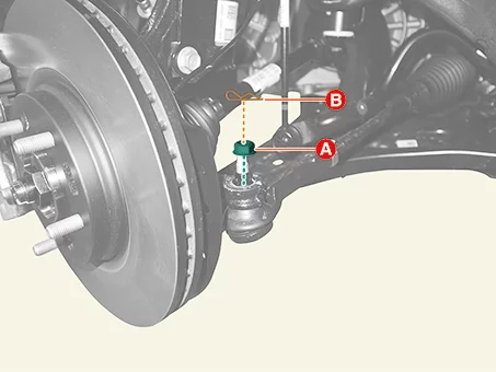
Separate the tie rod end ball joint from the front axle.
Remove the split pin (A).
Remove the lock nut (B).
Tightening torque : 34.3 - 44 N·m
Do not reuse the split pin.
Do not reuse the lock nut.
Be careful not to damage the boot of the link.
Use a hand tool when removing or installing the lock nut.
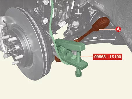
Separate the tie rod end ball joint (A) using the SST (09568 - 1S100).
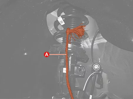
Secure the SST (09568 - 1S100) to prevent it from falling off using the wire (A).
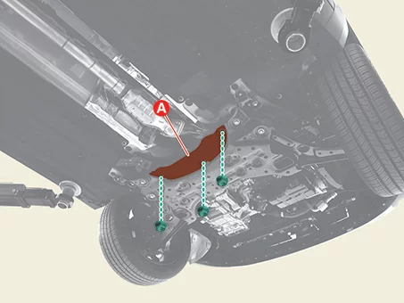
Remove the engine room rear under cover (A) after removing the nuts.
Tightening torque : 8.8 - 12,7 N·m
Remove the engine room under cover. G 1.6 T-GDI GAMMA II (Refer to Engine Mechanical System - "Engine Room Under Cover") G 2.0 MPI NU (Refer to Engine Mechanical System - "Engine Room Under Cover")
Remove the bolt (A), and then separate the roll rod bracket from the roll rod support bracket.
Tightening torque : 107.9 - 128 N·m
Do not reuse the roll rod bracket bolt.
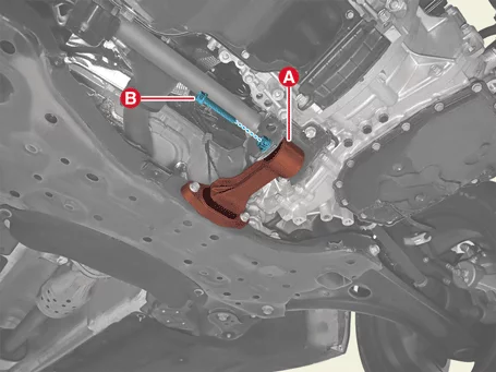
Remove the muffler rubber hanger (A) from the front sub frame.
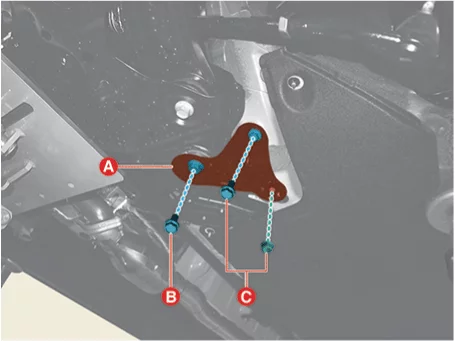
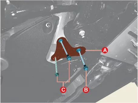
Remove the front sub frame stay (A). Tightening torque : (B) : 176.5 - 196 N·m (C) : 44.1 - 59 N·m [LH] [RH]
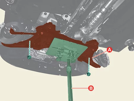
Support the front sub frame (A) with the jack (B) such as the transmission jack, and remove the front sub frame after removing the nut.
Tightening torque : 176.5 - 196 N·m
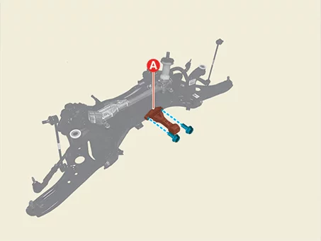
Remove the roll rod bracket (A) after removing the bolts.
Tightening torque : 49.0 - 64 N·m
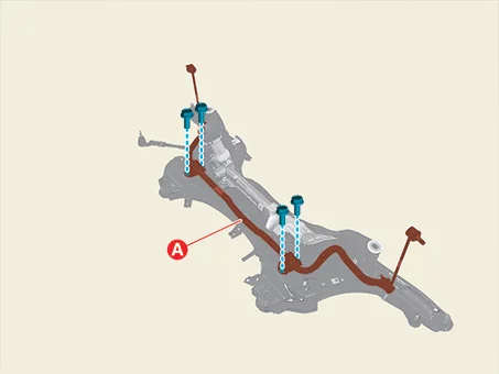
Remove the front stabilizer bar (A) after removing the bolts.
Tightening torque : 49.0 - 64 N·m
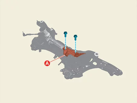
Remove the steering gear box heat protector (A) after removing the bolts.
Tightening torque : 7.8 - 11,8 N·m
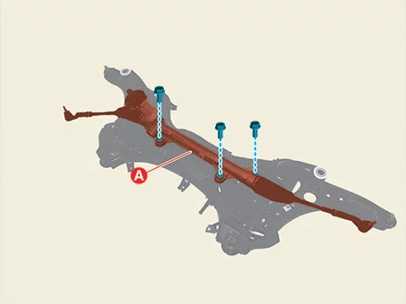
Remove the steering gear box (A) after removing the bolts.
Tightening torque : 88.3 - 108 N·m
When installing the steering gear box, pre-tighten the bolts first before tightening in torque.
Remove the front lower arm (A) after removing the bolts and nuts. Tightening torque : (B) : 117.7 - 137 N·m (C) : 156.9 - 176 N·m
Do not reuse the front lower arm bolt and nut.
Installation
Install in reverse order of removal.
Check the alignment. (Refer to Alignment - "Repair Procedures")