Single-Use Parts
Rear Driveshaft Assembly
In this manual: Single-Use Parts
15steps
~90min
4/5difficulty
Done 0 of 15
Contents:
Rear Driveshaft Components and Components Location
Component
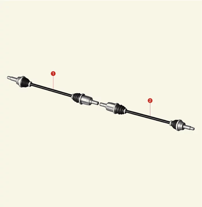
| 1. Rear Driveshaft (LH) | 2. Rear Driveshaft (RH) |
Rear Driveshaft Removal and Installation
Special Service Tool
| Tool Name / Number | Illustration | Description |
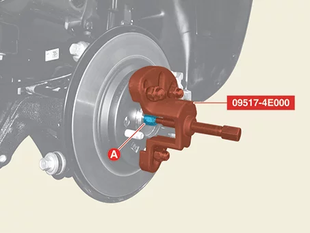
| CV joint puller 09517 - 4E000 |
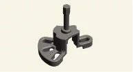 |
Used for removal of CV joint |
Removal
- Disconnect the battery negative (-) terminal.
- Remove the rear wheel and tires. (Refer to Suspension System - "Wheel")
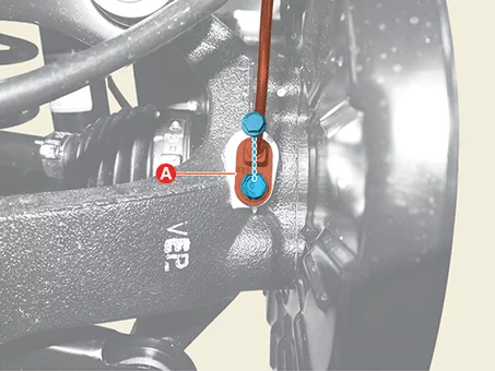
- Remove the rear wheel speed sensor clip (A).

- Remove the rear wheel speed sensor (A) after removing the bolt.
Tightening torque : 8.8 - 13,7 N·m
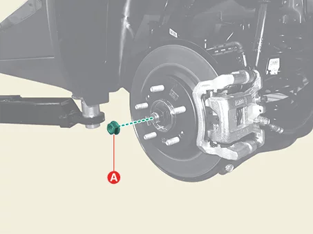
- Unlock the rear driveshaft lock nut caulking (A), by hammering on a chisel or suitable tool.
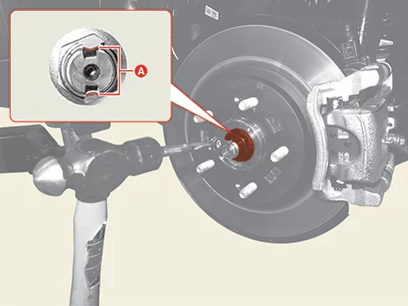
- Remove the rear driveshaft lock nut (A).
Tightening torque : 274.6 - 294 N·m
- Separate the rear driveshaft from the rear axle assembly using the SST (09517 - 4E000).
- Remove the rear brake disc. (Refer to Brake System - "Rear Brake Disc")
- Separate the rear upper arm (A) after removing the bolt and nut.
Tightening torque : 137.3 - 157 N·m
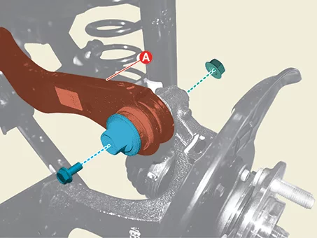

- Install the transmission jack and lift up the parts to prevent the bolts and nuts from damage when installing or removing.
- Be careful not to change the bolt, nut and washer installing position.
Fix the bolt and remove or install the nut.
- Remove the rear lower arm mounting nut and bolt (A).
Tightening torque : 137.3 - 157 N·m
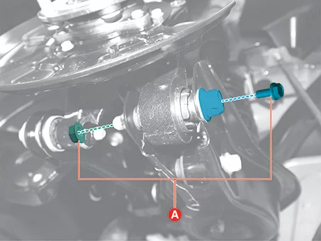
- Install the transmission jack and lift up the parts to prevent the bolts and nuts from damage when installing or removing.
- Be careful not to change the bolt, nut and washer installing position.
Fix the bolt and remove or install the nut. - Remove the rear trailing arm mounting bolts (A) and washers (B).
Tightening torque : 137.3 - 157 N·m
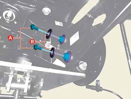
Install the transmission jack and lift up the parts to prevent the bolts and nuts from damage when installing or removing.
Fix the bolt and remove or install the nut. - Remove the rear axle assembly (A) after removing the rear assist arm bolt, washer and nut.
Tightening torque : 137.3 - 157 N·m
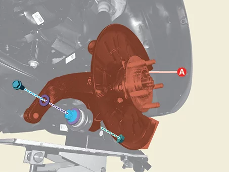
- Remove the rear driveshaft (A).
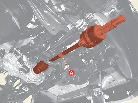
- Do not insert the pry bar too deep, as this may cause damage to the oil seal.
- Do not pull the driveshaft by excessive force it may cause components inside the joint kit to dislodge resulting in a torn boot or a damaged bearing.
- Plug the hole of the differential case with the oil seal cap to prevent contamination.
- Support the driveshaft properly.
- Replace the retainer ring each time the drive shaft is removed.
Installation
- Install in reverse order of removal.
- Check the alignment. (Refer to Suspension System - "Alignment")
Was this page helpful?