Accelerator Pedal Position Sensor (APS)
Specifications
Specification
| Accelerator | Output Voltage (V) [Vref = 5.0 V] | |
| Position | VPA1 | VPA2 |
| THA | 0,7 - 0,8 | 0,33 - 0,43 |
| THW | 4.13 - 4.22 | 2.04 - 2.13 |
Description and Operation
Description
The Accelerator Position Sensor (APS) is installed on the accelerator pedal module and detects the accelerator pedal angle.
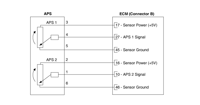
The APS is one of the most important sensors in the engine control system, so it consists of two sensors that have individual sensor power and ground lines.
The second sensor monitors the first sensor, and its output voltage is half that of the first.
If the ratio of sensor 1 and 2 is out of the allowable range (approx. 1/2), the diagnostic system judges it as abnormal.
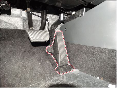
Circuit Diagrams
Wiring Diagram
Harness Connector

Repair Procedures
Inspection
The engine control system can be diagnosed more quickly for malfunctions using the Kia Diagnostic System (KDS). (Refer to Diagnostic Trouble Code Guide)
KDS provides the following information.
Self-diagnosis: Checks and displays diagnostic trouble codes (DTC).
Data list: Checks the input/output values of the system.
Active test: Checks the operating condition of the system.
Additional functions: System option control, zero point adjustment, and other functions.
Component Inspection
Connect the KDS to the Data Link Connector (DLC).
Turn the ignition on.
Measure the output voltage of APS 1 and 2 at C.T. and W.O.T.
Accelerator Output Voltage (V) [Vref = 5.0 V] Position VPA1 VPA2 THA 0,7 - 0,8 0,33 - 0,43 THW 3,98 - 4,22 1,93 - 2,17
Removal
Disconnect the negative battery cable.
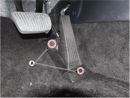
Open the mounting cover (A).
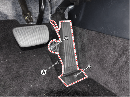
Remove the accelerator pedal module (A) after loosening the mounting bolts.
Tightening torque: 6.9–10.7 N·m
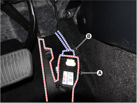
Disconnect the connector (A) from the accelerator pedal module (B).
Installation
Install in the reverse order of removal.
Test yourself
A quick Kia Optima DL3 quiz: every answer comes with an explanation and a link to the manual page.