Engine Control Module (ECM)
Components and Component Location
Component Location
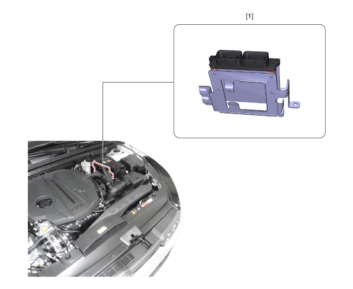
| 1. Engine Control Module (ECM) |
Circuit Diagrams
Connector and Terminal Function
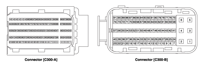
ECM Terminal Function
[Connector A]
| Pin | Function | Connected To |
| 1 | - | |
| 2 | ETC Motor [+] Control Output | ETC Motor |
| 3 | - | |
| 4 | - | |
| 5 | - | |
| 6 | - | |
| 7 | - | |
| 8 | - | |
| 9 | - | |
| 10 | - | |
| 11 | - | |
| 12 | - | |
| 13 | - | |
| 14 | - | |
| 15 | Sensor Ground | Engine Coolant Temperature Sensor (ECTS) |
| 16 | Engine Coolant Temperature Sensor (ECTS) Signal Input | Engine Coolant Temperature Sensor (ECTS) |
| 17 | Throttle Position Sensor (TPS) 2 Signal Input | Throttle Position Sensor (TPS) 2 [ETC Module] |
| 18 | - | |
| 19 | - | |
| 20 | - | |
| 21 | Sensor Power Supply (+5V) | Manifold Absolute Pressure Sensor (MAPS) |
| Camshaft Position Sensor (CMPS) [Bank 1 / Intake] | ||
| 22 | - | |
| 23 | ETC Motor [-] Control Output | ETC Motor [ETC Module] |
| 24 | - | |
| 25 | - | |
| 26 | - | |
| 27 | - | |
| 28 | - | |
| 29 | - | |
| 30 | - | |
| 31 | Electronic Load Signal Input (FR) | Generator |
| 32 | - | |
| 33 | - | |
| 34 | - | |
| 35 | - | |
| 36 | - | |
| 37 | Sensor Ground | Throttle Position Sensor (TPS) 1, 2 [ETC Module] |
| 38 | Throttle Position Sensor (TPS) 1 Signal Input | Throttle Position Sensor (TPS) 1 [ETC Module] |
| 39 | - | |
| 40 | Generator PWM Control Output | Generator |
| 41 | - | |
| 42 | Sensor Power Supply (+5V) | Throttle Position Sensor (TPS) 1, 2 [ETC Module] |
| 43 | - | |
| 44 | - | |
| 45 | - | |
| 46 | - | |
| 47 | - | |
| 48 | - | |
| 49 | - | |
| 50 | - | |
| 51 | - | |
| 52 | - | |
| 53 | - | |
| 54 | - | |
| 55 | - | |
| 56 | Sensor Ground | Camshaft Position Sensor (CMPS) [Bank 1/Exhaust] |
| 57 | - | |
| 58 | - | |
| 59 | - | |
| 60 | - | |
| 61 | Sensor Ground | Manifold Absolute Pressure Sensor (MAPS) |
| 62 | Manifold Absolute Pressure Sensor (MAPS) Signal Input | Manifold Absolute Pressure Sensor (MAPS) |
| 63 | Sensor Power Supply (+5V) | Camshaft Position Sensor (CMPS) [Bank 1 / Exhaust] |
| 65 | - | |
| 66 | - | |
| 67 | - | |
| 68 | - | |
| 69 | - | |
| 70 | - | |
| 71 | - | |
| 72 | - | |
| 73 | - | |
| 74 | Sensor Ground | Crankshaft Position Sensor (CKPS) |
| 75 | - | |
| 76 | - | |
| 77 | Camshaft Position Sensor (CMPS) [Bank 1 / Exhaust] Input Signal | Camshaft Position Sensor (CMPS) [Bank 1 / Exhaust] |
| 78 | Sensor Ground | Camshaft Position Sensor (CMPS) [Bank 1 / Intake] |
| 79 | - | |
| 80 | - | |
| 81 | - | |
| 82 | - | |
| 83 | VG (Virtual Ground) | Heated Oxygen Sensor [Bank 1 / Sensor 1] |
| 84 | VRC (Virtual Reference Control) | Heated Oxygen Sensor [Bank 1 / Sensor 1] |
| 85 | - | |
| 86 | - | |
| 87 | - | |
| 88 | - | |
| 89 | - | |
| 90 | - | |
| 91 | - | |
| 92 | - | |
| 93 | - | |
| 94 | - | |
| 95 | Crankshaft Position Sensor (CKPS) Signal Input | Crankshaft Position Sensor (CKPS) |
| 96 | - | |
| 97 | - | |
| 98 | Camshaft Position Sensor (CMPS) [Bank 1/Intake] Signal Input | Camshaft Position Sensor (CMPS) [Bank 1 / Intake] |
| 99 | Sensor Ground | Knock Sensor (KS) |
| 100 | Knock Sensor (KS) Signal Input | Knock Sensor (KS) |
| 101 | Intake Air Temperature Sensor (IATS) Signal Input | Intake Air Temperature Sensor (IATS) |
| 102 | - | |
| 103 | - | |
| 104 | VN (Nernst Cell Voltage) | Heated Oxygen Sensor (HO2S) [Bank 1 / Sensor 1] |
| 105 | VIP (Pump Current) | Heated Oxygen Sensor [Bank 1 / Sensor 1] |
[Connector B]
| Pin | Function | Connected To |
| 1 | Power Ground | Ground |
| 2 | Power Ground | Ground |
| 3 | Battery Power (B+) | Main Relay |
| 4 | Power Ground | Ground |
| 5 | Battery Power (B+) | Main Relay |
| 6 | Battery Power (B+) | Main Relay |
| 7 | - | |
| 8 | - | |
| 9 | - | |
| 10 | Accelerator Pedal Position Sensor (APS) 2 Signal Input | Accelerator Pedal Position Sensor (APS) 2 |
| 11 | Air Conditioning Pressure Sensor (APT) Signal Input | Air Conditioning Pressure Sensor (APT) |
| 12 | - | |
| 13 | - | |
| 14 | Sensor Power Supply (+5V) | Air Conditioning Pressure Sensor (APT) |
| 15 | - | |
| 16 | Sensor Power Supply (+5V) | Accelerator Pedal Position Sensor (APS) 2 |
| 17 | Sensor Power Supply (+5V) | Accelerator Pedal Position Sensor (APS) 1 |
| 18 | Main Relay Control Output | Main Relay |
| 19 | Fuel Pump Relay Control Output | Fuel Pump Relay |
| 20 | - | |
| 21 | - | |
| 22 | Injector Control Output (Cylinder #2) | Injector (Cylinder #3) |
| 23 | Injector Control Output (Cylinder #3) | Injector (Cylinder #3) |
| 24 | - | |
| 25 | - | |
| 26 | - | |
| 27 | Accelerator Pedal Position Sensor (APS) 1 Signal Input | Accelerator Pedal Position Sensor (APS) 1 |
| 28 | Sensor Ground | Heated Oxygen Sensor (HO2S) [Bank 1 / Sensor 2] |
| 29 | Heated Oxygen Sensor (HO2S) [Bank 1 / Sensor 2] Input Signal | Heated Oxygen Sensor (HO2S) [Bank 1 / Sensor 2] |
| 30 | - | |
| 31 | - | |
| 32 | - | |
| 33 | - | |
| 34 | Engine Start Relay Control Output | Engine Start Relay |
| 35 | CVVT Oil Control Valve (OCV) Control Output [Bank 1 / Exhaust] | CVVT Oil Control Valve (OCV) [Bank 1 / Exhaust] |
| 36 | CVVT Oil Control Valve (OCV) Control Output [Bank 1/Intake] | CVVT Oil Control Valve (OCV) [Bank 1 / Intake] |
| 37 | - | |
| 38 | A/C Relay Control Output | A/C Relay |
| 39 | Injector Control Output (Cylinder #4) | Injector (Cylinder #3) |
| 40 | Ignition Coil Control Output (Cylinder #2) | Ignition Coil (Cylinder No. 2) |
| 41 | Battery Power (B+) | Ignition Switch |
| 42 | - | |
| 43 | - | |
| 44 | - | |
| 45 | Sensor Ground | Accelerator Pedal Position Sensor (APS) 1 |
| 46 | Sensor Ground | Accelerator Pedal Position Sensor (APS) 2 |
| 47 | - | |
| 48 | - | |
| 49 | - | |
| 50 | Sensor Ground | Air Conditioning Pressure Sensor (APT) |
| 51 | - | |
| 52 | - | |
| 53 | - | |
| 54 | - | |
| 55 | - | |
| 56 | Injector Control Output (Cylinder No. 1) | Injector (Cylinder No. 1) |
| 57 | Ignition Coil Control Output (Cylinder No. 4) | Ignition Coil (Cylinder No. 4) |
| 58 | - | |
| 59 | LOCAL-CAN [Low] | Other Control Module, Data Link Connector (DLC) |
| 60 | P-CAN [Low] | Other Control Module, Data Link Connector (DLC) |
| 61 | Fuel Tank Level Sensor Signal Input | Fuel Level Sensor |
| 62 | - | |
| 63 | - | |
| 64 | - | |
| 65 | Stop Lamp Switch Input Signal | Brake Switch |
| 66 | Start Signal Input | Ignition Switch |
| 67 | Engine Speed Output Signal | Power Distribution Module (PDM) |
| 68 | Immobilizer Communication Line | Immobilizer Control Module |
| 69 | - | |
| 70 | - | |
| 71 | Purge Control Solenoid Valve (PCSV) Control Output | Purge Control Solenoid Valve (PCSV) |
| 72 | - | |
| 73 | Heated Oxygen Sensor (HO2S) [Bank 1 / Sensor 1] Heater Control Output | Heated Oxygen Sensor (HO2S) [Bank 1 / Sensor 1] |
| 74 | Ignition Coil Control Output (Cylinder #3) | Ignition Coil (Cylinder No. 3) |
| 75 | Memory Power (B+) | Engine Compartment Fuse and Relay Box (EMS ECU) |
| 76 | LOCAL-CAN [High] | Other Control Module, Data Link Connector (DLC) |
| 77 | C-CAN [High] | Other Control Module, Data Link Connector (DLC) |
| 78 | - | |
| 79 | Vehicle Speed Signal Input | ABS/ESC Control Unit |
| 80 | - | |
| 81 | Wiper Switch Input Signal | Integrated Body Control Unit (IBU) |
| 82 | - | |
| 83 | Brake Check Switch Input Signal | Brake Switch |
| 84 | - | |
| 85 | - | |
| 86 | Cooling Fan Relay Control Output | Cooling Fan Relay |
| 87 | - | |
| 88 | Variable Intake Solenoid (VIS) Valve Control Output | Variable Intake Solenoid (VIS) |
| 89 | - | |
| 90 | Heated Oxygen Sensor (HO2S) [Bank 1 / Sensor 2] Heater Control Output | Heated Oxygen Sensor (HO2S) [Bank 1 / Sensor 2] |
| 91 | Ignition Coil Control Output (Cylinder No. 1) | Ignition Coil (Cylinder No. 1) [Without Immobilizer] |
Repair Procedures
Inspection
The engine control system can be diagnosed more quickly for malfunctions using the Kia Diagnostic System (KDS). (Refer to Diagnostic Trouble Code Guide)
KDS provides the following information.
Self-diagnosis: Checks and displays diagnostic trouble codes (DTC).
Data list: Checks the input/output values of the system.
Active test: Checks the operating condition of the system.
Additional functions: System option control, zero point adjustment, and other functions.
Component Inspection
ECM Ground Circuit Inspection: Measure the resistance between the ECM ground and the chassis ground, using the rear of the ECM harness connector as the checkpoint on the ECM side. If a problem is found, repair it.
Specification: Below 1 Ω
ECM Connector Inspection: Disconnect the ECM connector and visually inspect the ground terminals on the ECM side and the harness side for bent pins or poor contact pressure. If a problem is found, repair it.
If no problem is found in Steps 1 and 2, the ECM may be faulty. Before replacing the ECM with a new one, make sure there are no DTCs, then re-check the vehicle. If DTCs are present, troubleshoot them first before replacing the ECM.
Retest the Original ECM: Install the original ECM (which may be faulty) in a known-good vehicle and check the vehicle. If the problem recurs, replace the original ECM with a new one. If the problem does not occur, it is an intermittent problem.
Removal
Disconnect the negative battery cable.
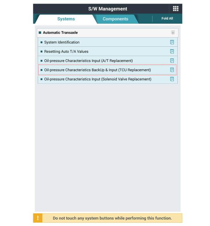
Perform the oil pressure characteristic backup procedure using KDS when replacing with a new ECM.
Remove the air cleaner assembly.
(Refer to Engine Mechanical System - "Air Cleaner")
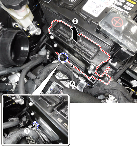
Disconnect the ECM connector (A).
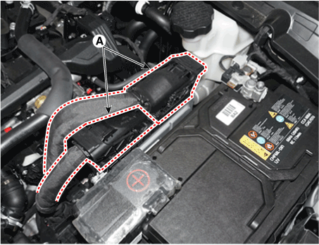
Remove the TCM (A) by pulling it in the direction indicated by the arrow.
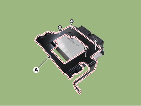
Remove the bracket (A) by loosening the bolts.
Tightening Torque: 9.8–11.8 N·m
Installation
Install in the reverse order of removal.
Perform the ECM reset and learning procedure using KDS after replacement.
(Engine Control Module (ECM) - Adjustment)
Adjustment
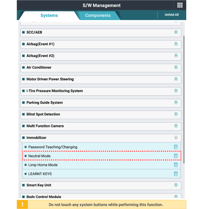
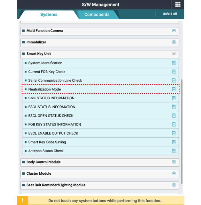
Perform the neutral mode using KDS when replacing with a reused ECM.
[Without Smart Key]
[Smart Key]
Perform the Key Teaching procedure using KDS.
[Without Smart Key]
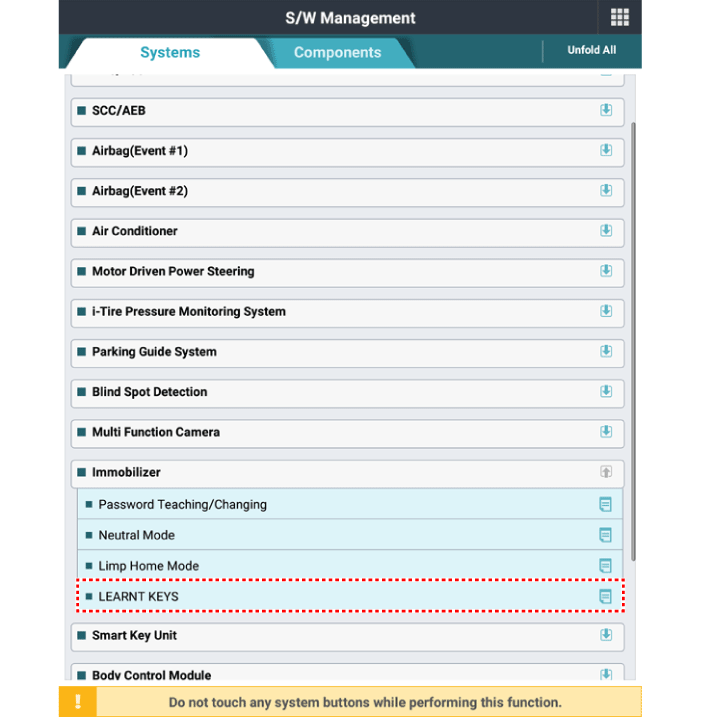
[Smart Key]
Turn the ignition on, then off, using the smart key or start button. The ECM will then automatically receive the smart key information.
Perform the VIN registration procedure using KDS.
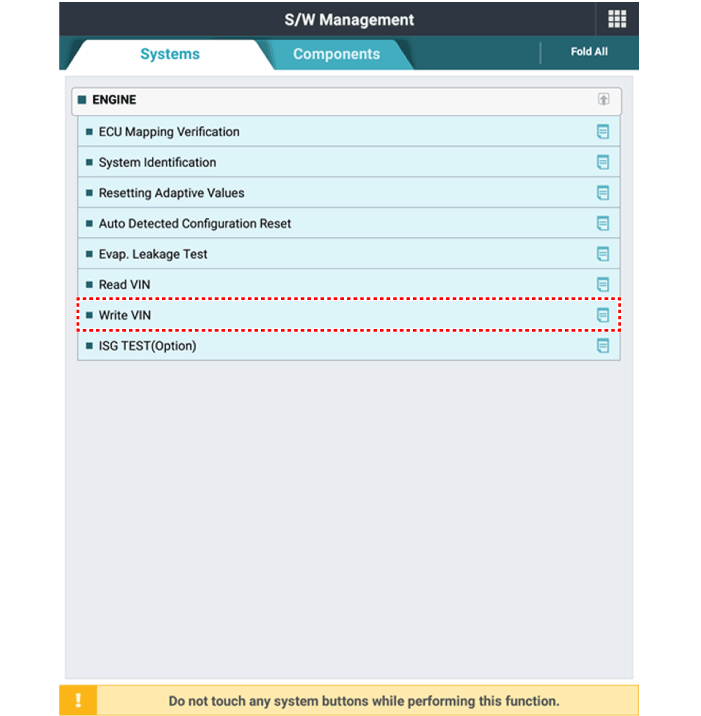
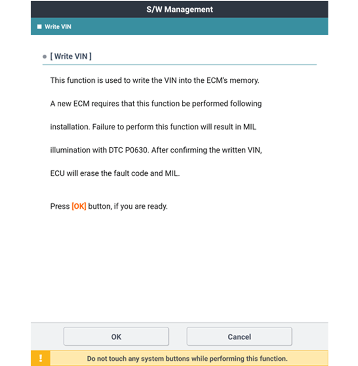
Perform the oil pressure characteristics input procedure using the KDS.
Perform the ETC module learning procedure.
(Refer to Electronic Throttle Control System - "Adjustment")
Perform the TCM learning procedure.
(Refer to "Automatic Transmission Control System - Adjustment")
Test yourself
A quick Kia Optima DL3 quiz: every answer comes with an explanation and a link to the manual page.