Four Wheel Drive (4WD) Low Switch Circuit Range / Performance (P2772)
In this manual: Engine, Hybrid System
8steps
~48min
2/5difficulty
Done 0 of 8
DESCRIPTION
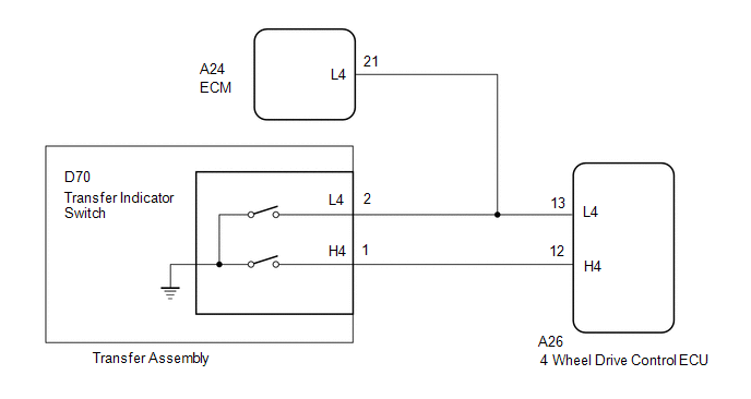
When the transfer is switching between 4H and 4L, the H4 and L4 terminals of the transfer indicator switch are in one of the ON/OFF combinations listed in the table below.
Terminal
In 4H
Switching between 4H and 4L
In 4L
H4
OFF (OPEN)
ON (GND)
ON (GND)
L4
OFF (OPEN)
OFF (OPEN)
ON (GND)
This DTC is detected when the 4WD HIGH position and 4WD LOW position judgment signals do not match.
DTC Code
DTC Detection Condition
Diagnosis Condition
Malfunction Status
Malfunction Time
Other
Trouble Area
P2772
Ignition switch is ON and engine is running
H4 terminal signal is OFF (OPEN) and L4 terminal signal is ON (GND)
1 second or more
1 trip detection logic
Wire harness and connector
4 wheel drive control ECU
Transfer indicator switch
WIRING DIAGRAM
PROCEDURE
CHECK HARNESS AND CONNECTOR (4 WHEEL DRIVE CONTROL ECU - TRANSFER INDICATOR SWITCH)
(a) Disconnect the A26 4 wheel drive control ECU connector.
(b) Disconnect the D70 transfer indicator switch connector.
(c) Disconnect the A24 ECM connector.
(d) Measure the resistance according to the value(s) in the table below.
Standard Resistance:
Tester Connection
Condition
Specified Condition
A26-13 (L4) - D70-2 (L4)
Always
Below 1 Ω
A26-12 (H4) - D70-1 (H4)
Always
Below 1 Ω
A26-13 (L4), D70-2 (L4) or A24-21 (L4) - Body ground
Always
10 kΩ or higher
A26-12 (H4) or D70-1 (H4) - Body ground
Always
10 kΩ or higher
A26-13 (L4), D70-2 (L4) or A24-21 (L4) - A26-12 (H4) or D70-1 (H4)
Always
10 kΩ or higher
NG
REPAIR OR REPLACE HARNESS OR CONNECTOR
OK
CHECK 4 WHEEL DRIVE CONTROL ECU (ECU OUTPUT VOLTAGE)
(a) Disconnect the A24 ECM connector.
(b) Disconnect the transfer indicator switch connector.
(c) Measure the voltage according to the value(s) in the table below.
Standard Voltage:
Tester Connection
Switch Condition
Specified Condition
D70-2 (L4) - Body ground
Ignition switch ON
4 to 6 V
D70-1 (H4) - Body ground
Ignition switch ON
4 to 6 V
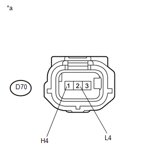
Text in Illustration
*a
Front view of wire harness connector
(to Transfer Indicator Switch)
NOTICE:
Turning the ignition switch on with the ECM connector disconnected causes other DTCs to be stored. Clear the DTCs after performing this inspection.