Engine, Hybrid System
Four Wheel Drive (4WD) Range Signal Circuit Range / Performance (P279E)
Done 0 of 8
DESCRIPTION
This DTC is detected if the transfer position switch 2-4 terminal and LO terminal signals are simultaneously received.
WIRING DIAGRAM 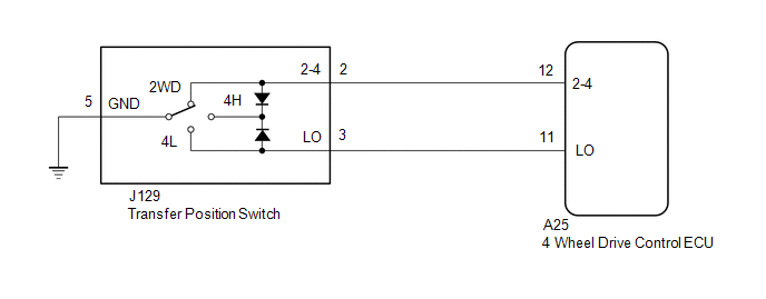
PROCEDURE
CHECK HARNESS AND CONNECTOR (4 WHEEL DRIVE CONTROL ECU - TRANSFER POSITION SWITCH)
(a) Disconnect the A25 4 wheel drive control ECU connector.
(b) Disconnect the J129 transfer position switch connector.
(c) Measure the resistance according to the value(s) in the table below.
Standard Resistance:
Tester Connection | Condition | Specified Condition |
A25-12 (2-4) - J129-2 (2-4) |
Always |
Below 1 Ω |
A25-11 (LO) - J129-3 (LO) |
Always |
Below 1 Ω |
J129-5 (GND) - Body ground |
Always |
Below 1 Ω |
A25-12 (2-4) or J129-2 (2-4) - Body ground |
Always |
10 kΩ or higher |
A25-11 (LO) or J129-3 (LO) - Body ground |
Always |
10 kΩ or higher |
A25-12 (2-4) or J129-2 (2-4) - A25-11 (LO) or J129-3 (LO) |
Always |
10 kΩ or higher |
| NG |
 |
REPAIR OR REPLACE HARNESS OR CONNECTOR |
| OK |
 |
|
CHECK TRANSFER POSITION SWITCH
(a) Remove the transfer position switch with its connector still connected (See page  ). 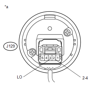
(b) Measure the voltage according to the value(s) in the table below.
Standard Voltage:
Tester Connection | Switch Condition | Specified Condition |
J129-2 (2-4) - Body ground |
Ignition switch ON
2WD position |
Below 1 V |
Ignition switch ON
4H position |
Below 1.5 V |
Ignition switch ON
4L position |
10.5 to 14 V |
J129-3 (LO) - Body ground |
Ignition switch ON
2WD position |
10.5 to 14 V |
Ignition switch ON
4H position |
Below 1.5 V |
Ignition switch ON
4L position |
Below 1 V |
Text in Illustration
*a |
Component with harness connected
(Transfer Position Switch) |
| OK |
|
REPLACE 4 WHEEL DRIVE CONTROL ECU |
| NG |
|
REPLACE TRANSFER POSITION SWITCH |
|
Was this page helpful?