DESCRIPTION
This DTC is detected when the 4 wheel drive control ECU, which monitors the B terminal voltage, determines that the standard voltage is not met and detects a B terminal system malfunction.
WIRING DIAGRAM 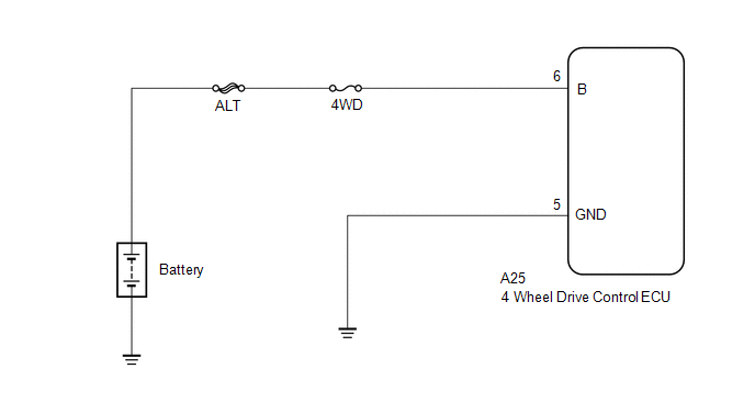
NOTICE:
- Inspect the fuses for circuits related to this system before performing the following inspection procedure.
- If only past DTCs are output, battery depletion may have occurred in the past.
PROCEDURE
INSPECT BATTERY
(a) Inspect the battery (3UR-FE: See page  , 3UR-FBE: See page , 1UR-FE: See page ).
| NG |
 |
REPLACE BATTERY |
| OK |
 |
|
CHECK BATTERY TERMINAL
(a) Check the battery terminals (3UR-FE: See page , 3UR-FBE: See page , 1UR-FE: See page ).
| NG |
|
REPAIR BATTERY TERMINAL OR REPLACE BATTERY |
| OK |
|
|
CHECK HARNESS AND CONNECTOR (B TERMINAL)
(a) Disconnect the 4 wheel drive control ECU connector. |
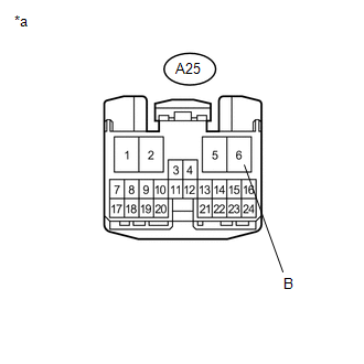 |
(b) Measure the voltage according to the value(s) in the table below.
Standard Voltage:
Tester Connection | Condition | Specified Condition |
A25-6 (B) - Body ground |
Always |
11 to 14 V |
Text in Illustration
*a |
Front view of wire harness connector
(to 4 Wheel Drive Control ECU) |
| NG |
|
REPAIR OR REPLACE HARNESS OR CONNECTOR |
| OK |
|
|
CHECK HARNESS AND CONNECTOR (GND TERMINAL)
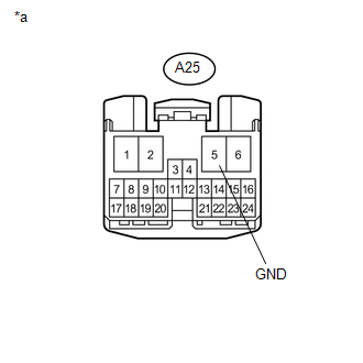
(a) Disconnect the 4 wheel drive control ECU connector.
(b) Measure the resistance according to the value(s) in the table below.
Standard Resistance:
Tester Connection | Condition | Specified Condition |
A25-5 (GND) - Body ground |
Always |
Below 1 Ω |
Text in Illustration
*a |
Front view of wire harness connector
(to 4 Wheel Drive Control ECU) |
| NG |
|
REPAIR OR REPLACE HARNESS OR CONNECTOR |
| OK |
|
|
RECONFIRM DTC
(a) Clear the DTCs (See page ).
(b) Operate the transfer position switch.
(c) Check if the same DTC is output (See page ). Result
Result | Proceed to |
DTC is output |
A |
DTC is not output |
B |
| A |
|
REPLACE 4 WHEEL DRIVE CONTROL ECU |
| B |
|
CHECK INTERMITTENT PROBLEMS |
|