Bumper. Bumper, front
- Assembly overview – bumper cover
- Assembly overview – bumper carrier
- Removing and installing bumper cover
- Removing and installing bumper carrier
- Installing holder for park assist steering sender
- Moving bumper carrier to and back from service position
- Removing and installing radar sensor cover
- Removing and installing front spoiler bracket
- Removing and installing trim
- Removing and installing number plate carrier
- Removing and installing towing eye cap, one-piece design
- Removing and installing centre air intake grille
Assembly overview – bumper cover
Assembly overview – bumper cover

1 - Lower guide profile
❏ Qty. 2
2 - Expanding nut
❏ Qty. 6
3 - Upper guide profile
❏ Qty. 2
4 - Bolt
❏ Qty. 4
❏ 2 N·m
5 - Bolt
❏ Qty. 8
❏ 2 N·m
6 - Light conductor for contour lighting in radiator grille, front left, L362/L363/trim panel
❏ Depending on equipment/version
❏ Qty. 2
❏ → Rep. gr.94; Headlights; Removing and installing light conductor for contour lighting in radiator grille at front [L362]/[L363]
❏ → Rep. gr.63; Removing and installing trim
7 - Clips
❏ Qty. 29
8 - Seal
9 - Nut
❏ Qty. 4
❏ 2,5 N·m
10 - Bolt
❏ Qty. 2
❏ 2 N·m
11 - Bolt
❏ Qty. 6
❏ 2 N·m
12 - Bumper cover
❏ With front spoiler
❏ → Rep. gr.63; Removing and installing bumper cover
13 - Front spoiler bracket
❏ → Rep. gr.63; Removing and installing front spoiler bracket
14 - Bolt
❏ Qty. 8
❏ 2 N·m
15 - Centre air intake grille
❏ → Rep. gr.63; Removing and installing centre air intake grille
16 - Clip
❏ Qty. 4
17 - Number plate carrier
18 - Cover
❏ → Rep. gr.63; Removing and installing radar sensor cover
19 - Radar sensor cover
❏ → Rep. gr.63; Removing and installing radar sensor cover
20 - Radar sensor
❏ → Driver assist systems; Rep. gr.98; Senders/sensors/control units; Removing and installing adaptive cruise control unit [J428]
21 - Towing eye cap
❏ → Rep. gr.63; Removing and installing towing eye cap
Assembly overview – bumper carrier
Assembly overview – bumper carrier

1 - Bumper carrier
❏ → Rep. gr.63; Moving bumper carrier to and back from service position
❏ → Rep. gr.63; Removing and installing bumper carrier
2 - Bolt
❏ Qty. 8
❏ 55 N·m
3 - Bolt
❏ Qty. 4
❏ 30 N·m
4 - Support profile
5 - Pop rivet
❏ Qty. 4
6 - Expanding nut
❏ Qty. 2
7 - Foam element
8 - Air supply
❏ → Electric drive, rear-wheel drive EIP220 and all-wheel drive EIA200, EIP220; Rep. gr.19; Radiator/radiator fan; Assembly overview – radiator/radiator fan
❏ → Electric drive, rear-wheel drive EIP220 and all-wheel drive EIA200, EIP220; Rep. gr.19; Radiator/radiator fan; Removing and installing radiator module
Removing and installing bumper cover
Removing and installing bumper cover
Special tools and workshop equipment required
♦ Setting gauge -3371-
When renewing components, identification labels from old parts indicating the corresponding spare part numbers in the → Electronic parts catalogue (ETKA) must be attached to the respective new parts in accordance with registration regulations.
Renew any illegible or damaged identification labels and information or warning signs found on components of this vehicle, and affix the new ones in the same location. For allocation, see → Electronic parts catalogue (ETKA).
Removing
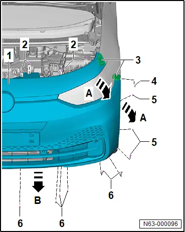
– Unscrew bolts -2- on left and right.
– Unscrew bolts -5- in wheel housing on left and right.
– Unscrew bolts -4- on left and right in wheel housing from below.
– Unscrew bolts -6-.
Important
● Further removal requires the assistance of a 2nd person.
– Pull bumper cover -1- out of guide fasteners on left and right -3- of wing -arrows A-.
– Pull bumper cover -1- off vehicle making sure to keep it level while doing so -arrows B-.
– Disconnect electrical connectors.
Installing
Install in reverse order of removal, observing the following:
Important
● Installation requires the assistance of a 2nd person.
– Guide bumper cover towards vehicle keeping it absolutely parallel and making sure that front wheel housing liner is properly seated.
– Check gaps with setting gauge -3371-, observing → Rep. gr.00; front gaps while doing so.
– Adjust/calibrate adaptive cruise control → Driver assist systems; Rep. gr.98; Adaptive cruise control; adjusting/calibrating adaptive cruise control.
Tightening torques
♦ → Rep. gr.63; Assembly overview – bumper cover
Removing and installing bumper carrier
Removing and installing bumper carrier
Special tools and workshop equipment required
♦ guide pins -T10625-
♦ guide pins -T10625/1-
♦ guide pins -T10625/2-
Removing
– Remove radiator package → Power unit; Rep. gr.19; Radiator/radiator fan; Removing and installing radiator module.
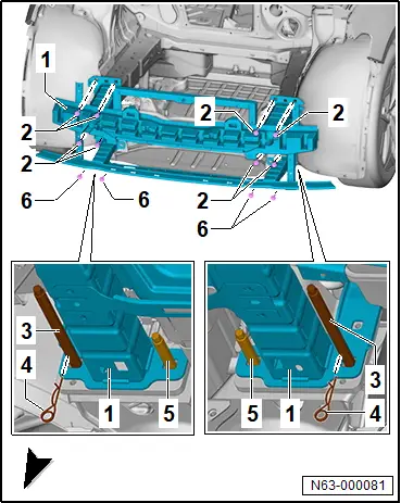
– Unscrew inner bolts -6- on left and right of longitudinal member.
– Screw in short guide pins -T10625/2- -5- in place of inner bolts -6-.
– Unscrew outer bolts -6- on left and right of subframe.
– Screw in long guide pins -T10625/1- -3- in place of outer bolts -6-.
– Secure split pin -4-.
– Unscrew bolts -2- from longitudinal member on left and right.
– Pull bumper carrier with attachments -1- on guide pins in direction of travel. Take care of electrical wires when doing this. Disconnect connectors if necessary.
– Detach electrical wires from bumper carrier.
A second person is required to assist with the following work.
– Pull out split pin.
– Pull bumper carrier off guide pins -T10625-.
Installing
Install in reverse order of removal, observing the following:
– Screw in bolts -2- but do not tighten.
– Screw out long guide pins -T10625/1- -3- on left and right.
– Screw outer bolts -6- into subframe on left and right, firmly but no more than finger-tight.
– Screw short guide pins -T10625/2- -4- out of longitudinal member on left and right.
– Screw inner bolts -6- into longitudinal member on left and right, firmly but no more than finger-tight.
– Tighten bolts -2- and -6-.
Tightening torques
♦ → Rep. gr.63; Assembly overview – bumper carrier
Installing holder for park assist steering sender
Installing holder for park assist steering sender
Special tools and workshop equipment required
♦ Attachment device for PDC holder -VAS 6614/7-
♦ Clip, M-shaped -VAS 6872/3-
♦ Drill bit -VAS 6614/4-
♦ Hand set -VAS 6872/1-
♦ Hole punch 26.5mm -VAS 895 003-
The holder for park assist steering sender will henceforth be referred to as “holder”.
The installation is described for one of the holders as an example.
The holder is installed after the bumper cover has been painted.
Installing
Markings -2- for holder are located on inside of bumper cover -1-.
– Predrill hole using drill bit -VAS 6614/4- -3-.

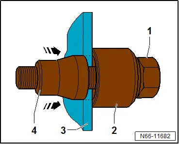
– Fit screw-hole punch, 26.5 mm -VAS 895 003- with screw head -1-, washer and counter-support -2- from inside of bumper cover -3-.
– Screw on punch -4- until just before bumper cover -3-.
– Press punch -4- against bumper cover -3-.
– Tighten bolt head -1-.
 NOTICE
Risk of damage to component surfaces due to turning the screw-hole punch.
– Hold the screw-hole punch firmly.
– Turn screw head -1- to pull punch -4- in direction of -arrow- through material of bumper cover -3-.
– Remove screw-hole punch, 26.5 mm -VAS 895 003- from bumper cover -3-.
– Centre holder -1- via hole, and use attachment device for PDC holder -VAS 6614/7- -2- to secure holder in direction of -arrow- to bumper cover -3-.

– Refer to figure for positions of clip, M-shaped -VAS 6872/3- -2- on holder -1-.
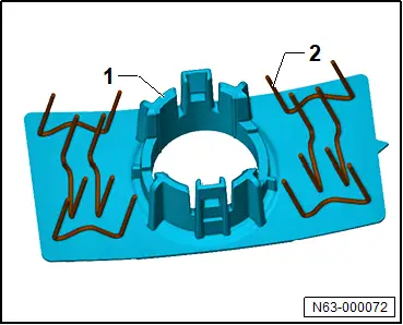
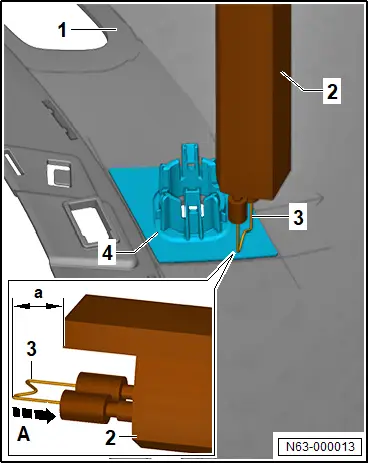
– Secure clip, M-shaped -VAS 6872/3- -3- in direction of -arrow A- in hand set -VAS 6872/1- -2-.
NOTICE
Risk of damage to bumper cover due to inaccurate adjustment of spacer.
– Observe the exact distance.
If the distance is too low, the holder -4- will not be secured properly.
If the distance is too high, the clips -3- will leave marks on the bumper cover -1-.
– Adjust distance -A- to 3 mm.
– Allow clip -3- to melt in without applying force.
– Switch off -hand set- when spacer makes contact with holder.
– Allow the clip to cool down for 10 s. Do not move -hand set- during this period.
– Once the cool-down period has elapsed, pull off hand set -2-, and proceed analogously for the remaining clips -3-.
– Once all clips -3- have been installed, cut off ends of all clips -3-.
Moving bumper carrier to and back from service position
Moving bumper carrier to and back from service position
Special tools and workshop equipment required
♦ Adapter -T10467-
♦ Adapter -T10480-
♦ guide rod -T10093-
♦ guide rod -T10228-
Moving bumper carrier to service position
– Remove headlight → Electrical system; Rep. gr.94; Headlights; Removing and installing headlights.
– Remove lock carrier → Rep. gr.50; Removing and installing lock carrier.
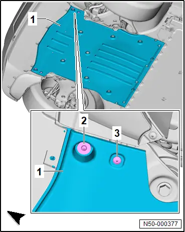
– Unscrew bolts -2- and -3- on left and right of front underbody cladding -1- → Rep. gr.66; Removing and installing front underbody cladding.
– Unscrew bolt from longitudinal member on both sides of vehicle, and screw guide pin -T10093- -4- into longitudinal member.
– Unscrew bolt -2- from longitudinal member on both sides of vehicle.
– Unscrew centre bolts -6- on both sides of vehicle, and screw in guide pin -T10228- -5-.
– Unscrew outer bolts -6- on both sides of vehicle.
– Disconnect electrical connectors.
– Pull bumper carrier with attachments -1- on guide pins -4- and -5- towards front while noting electrical wiring.
– Screw in adapter -T10467- -3- as a securing means on both sides of vehicle between bumper carrier and longitudinal member.
– Screw in adapter -T10480- -7- as a securing means on both sides of vehicle between bumper carrier and longitudinal member.
– Screw in bolts -2- and -6- into adapters -3- and -7- on both sides of vehicle.
– Tighten bolts -2- and -6- on both sides of vehicle.

Moving bumper carrier back from service position
Move back from service position in the reverse order observing the following:
Tightening torques
♦ → Rep. gr.63; Assembly overview – bumper carrier
Removing and installing radar sensor cover
Removing and installing radar sensor cover
Special tools and workshop equipment required
♦ wedge -T10383/2-
 NOTICE
Functional restrictions possible due to treatment/modifications of the radar sensor cover.
– Do not repair, paint or cover the radar sensor cover with film.
– Do not cover the radar sensor with other components.
– If the radar sensor cover is damaged, renew it.
Removing
– Remove number plate carrier → Rep. gr.63; Removing and installing number plate carrier.
NOTICE
Risk of damage to the bumper cover when releasing the fastener.
– Mask off bumper cover in area of radar sensor cover with commercially available adhesive tape.
– Using wedge -T10383/2- (qty. 2), release locking device -3- and locking devices indicated by -arrows- in direction of -arrow-.
– Lever radar sensor cover -1- together with cover -4- out of bumper cover -5-.
– Release fasteners of radar sensor cover -1- from cover -4-, and pull radar sensor cover -1- off cover -4-.

Installing
Install in reverse order of removal, observing the following:
– Radar sensor cover and cover must be engaged completely prior to installing.
Removing and installing front spoiler bracket
Removing and installing front spoiler bracket
Removing
– Unscrew bolts -2 and 3-.
– Release bumper cover locking devices -5- from front spoiler bracket -4-.
– Pull front spoiler bracket off bumper cover.

Installing
Install in reverse order of removal, observing the following:
Important
● Attach front spoiler bracket making sure it engages audibly.
Tightening torques
♦ → Rep. gr.63; Assembly overview – bumper cover
♦ → Rep. gr.66; Assembly overview – front wheel housing liner
Removing and installing trim
Removing and installing trim
Removal and installation are described for the left side of vehicle as an example.
Removing
– Remove bumper cover → Rep. gr.63; Removing and installing bumper cover.
– Press together fasteners -2- in direction of -arrow A-, and release them.
– Detach trim panel -1- from bumper cover -3- in direction of -arrow B-.

Installing
Install in reverse order of removal, observing the following:
– Fit trim panel so that fasteners can be heard to engage.
Removing and installing number plate carrier
Removing and installing number plate carrier
Removing
– Unclip clips -2-.
– Detach number plate carrier -1- from bumper cover.

Installing
Install in reverse order of removal, observing the following:
Bumper cover without drillings
– Remove bumper cover → Rep. gr.63; Removing and installing bumper cover.
The positions of holes to be drilled -arrows- are marked on the inner side of the bumper cover -1-.
– Drill required amount of holes (8 mm in dia.) -arrows- in bumper cover -1-.

– Install bumper cover → Rep. gr.63; Removing and installing bumper cover.
Removing and installing towing eye cap, one-piece design
Removing and installing towing eye cap, one-piece design
The one-piece towing eye cap will henceforth be referred to as “cap”.
Removing
Note
Shape of cap depends on model.
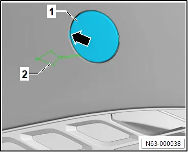
– Press cap -1- in area of -arrow-, and release it.
– Detach cap -1-, and guide out tether -2-.
– Remove cap -1-.
Installing
Install in reverse order of removal, observing the following:
– Insert cap into recess, and press it on until fastener can be heard to engage.
Removing and installing centre air intake grille
Removing and installing centre air intake grille
Removing
– Remove bumper cover → Rep. gr.63; Assembly overview – bumper cover.
– Disconnect electrical connectors.
– Pull off electrical wires.
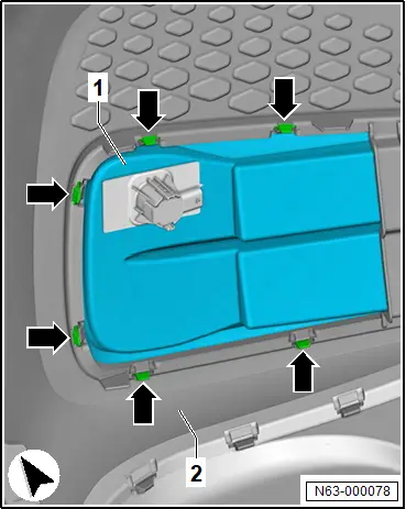
– Detach fasteners -arrows- on both sides of vehicle.
– Pull centre air intake grille -1- off bumper cover -2-.
Installing
Install in reverse order of removal.