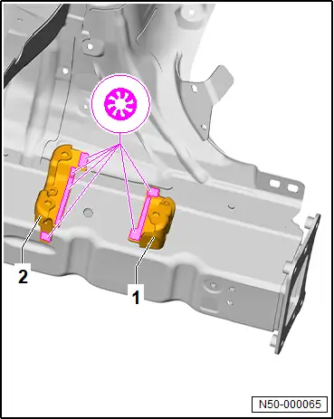
Body front. Longitudinal member
- Assembly overview – front left longitudinal member (part section)
- Assembly overview – front left longitudinal member, part section (second separating cut)
- Assembly overview – front right longitudinal member (part section)
- Assembly overview – front right longitudinal member, part section (second separating cut)
- Assembly overview – upper longitudinal member
- Assembly overview - upper inner longitudinal member
- Renewing front left longitudinal member (part section)
- Renewing front left longitudinal member, part section (2nd separating cut)
- Renewing front right longitudinal member (part section)
- Renewing front right longitudinal member, part section (second separating cut)
- Renewing upper longitudinal member
- Renewing upper inner longitudinal member
- Assembly overview - battery tray
- Renewing battery tray
Assembly overview – front left longitudinal member (part section)
Assembly overview – front left longitudinal member (part section)

1 - Front longitudinal member
❏ → Rep. gr.50; Renewing front left longitudinal member (part section)
2 - Separating cut
3 - Bonded area
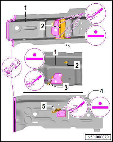
Assembly overview – front left longitudinal member, part section (second separating cut)
Assembly overview – front left longitudinal member, part section (second separating cut)

1 - Front longitudinal member
❏ → Rep. gr.50; Renewing front left longitudinal member, part section (2nd separating cut)
2 - Cross panel for front longitudinal member
3 - Retainer for brake hose
4 - Cover plate for front longitudinal member
5 - Moulded foam insert
❏ → Rep. gr.00; Moulded foam inserts
6 - Partition
7 - Separating cut
8 - Partition plate for front longitudinal member
9 - Rear battery tray
10 - Front battery tray
11 - Mounting bracket for subframe
12 - Bonded areas
Assembly overview – front right longitudinal member (part section)
Assembly overview – front right longitudinal member (part section)
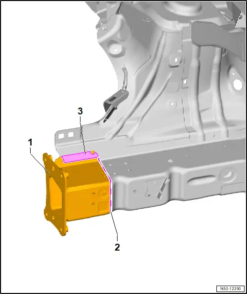
1 - Front longitudinal member
❏ → Rep. gr.50; Renewing front right longitudinal member (part section)
2 - Separating cut
3 - Bonded area
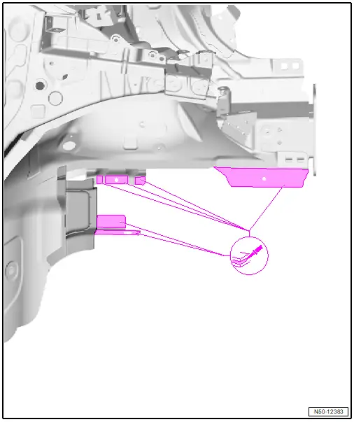
Assembly overview – front right longitudinal member, part section (second separating cut)
Assembly overview – front right longitudinal member, part section (second separating cut)

1 - Front longitudinal member
❏ → Rep. gr.50; Renewing front right longitudinal member, part section (second separating cut)
2 - Front longitudinal member end plate
3 - Retainer for brake hose
4 - Cover plate for front longitudinal member
5 - Moulded foam insert
❏ → Rep. gr.00; Moulded foam inserts
6 - Partition
7 - Separating cut
8 - Partition plate for front longitudinal member
9 - Pipe set bracket
10 - Mounting bracket for subframe
11 - Bonded areas
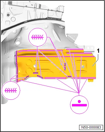
Assembly overview – upper longitudinal member
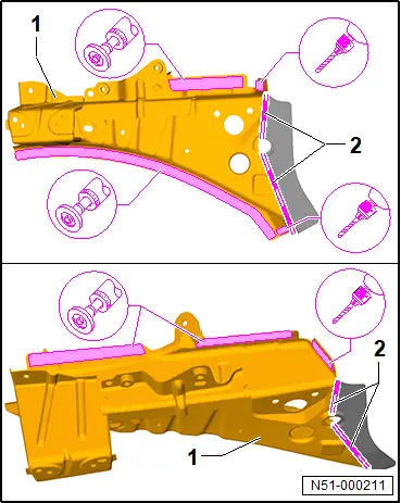
Assembly overview – upper longitudinal member
Overview is shown for left side of vehicle as an example.
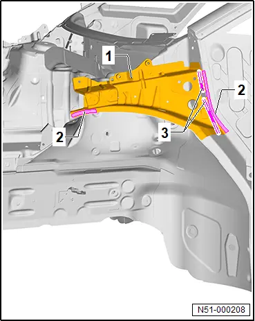
1 - Upper longitudinal member
❏ → Rep. gr.50; Renewing upper longitudinal member
2 - Bonded areas
3 - Separating cut
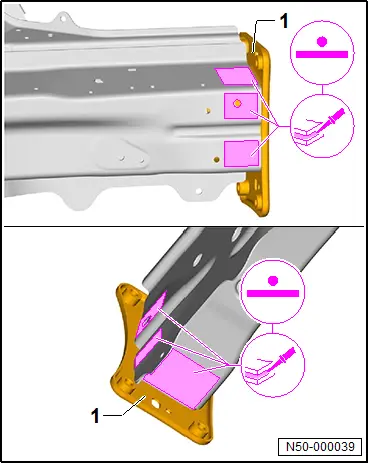
Assembly overview - upper inner longitudinal member
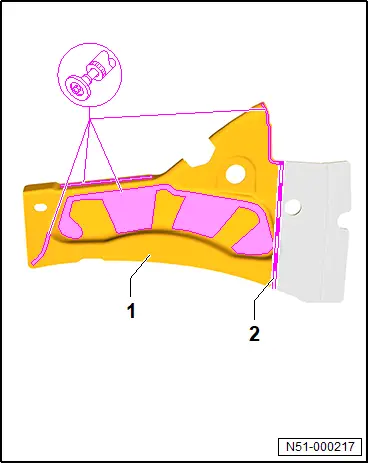
Assembly overview - upper inner longitudinal member
Overview is shown for left side of vehicle as an example.

1 - Upper inner longitudinal member
❏ → Rep. gr.50; Renewing upper inner longitudinal member
2 - Separating cut
3 - Bonded areas
Renewing front left longitudinal member (part section)
Renewing front left longitudinal member (part section)
 WARNING
Gases/ vapours hazardous to health are generated when welding, soldering or cutting using tools which produce sparks in foam-treated areas.
– Do not weld, solder or cut closer than 15 mm to moulded foam inserts.
– Use an extraction system during work.
 NOTICE
If separating cuts are made too deep, underlying reinforcement could be damaged.
– Only make separating cuts with body saw.
– Rewelding of reinforcements is not permitted due to safety reasons.
NOTICE
If welds are positioned too far on outside, strength could be impaired
– RP weld points must be placed as far as possible from outer edge of welding flange.
NOTICE
Strength could be impaired if continuous seam is changed
– SG continuous weld seam must not be reworked (ground or smoothed).
NOTICE
If adhesive is applied prematurely, bond could be impaired
– New part must be welded in within 90 minutes.
Observe safety information → Rep. gr.00; Safety information
Only tools and workshop equipment authorised by Volkswagen AG may be used → Rep. gr.00; Tools.
Removing
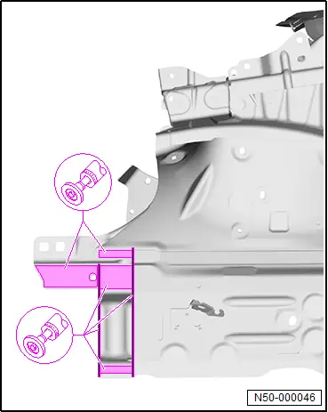
– Mark separating cut -2- all around on front longitudinal member -1- in accordance with dimension -a-, and cut in a straight line.
♦ Dimension -a- = 83 mm
– Separate original joint.
– Remove longitudinal member part section -1-.
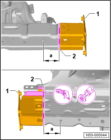
– Mark parting cut -2- on front longitudinal member -1- in accordance with dimension -a-, and make parting cut in a straight line.
♦ Dimension -a- = 40 mm
– Separate original joint.
– Remove remainder of longitudinal member -1-.

– Remove remaining material.
– Completely remove adhesive residue.
– Sand bonding and welding surfaces down to bare metal, and clean them.
Installing
Replacement parts
♦ For allocation of 2-pack body adhesive, see → Electronic parts catalogue (ETKA)
Important
● New parts must be adapted and attached with the vehicle standing on the straightening bracket set.
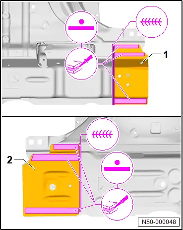
– Sand bonding and welding surfaces on new part -1- down to bare metal, and clean them.

– Transfer separating cut -2- to new part -1-, and cut in a straight line.
– Transfer separating cut -3- to new part -4-, and cut in a straight line.
– Sand bonding and welding surfaces down to bare metal, and clean them.

– Apply 2-component body adhesive over entire area of RP spot weld seam.
– Adapt new part -1- and -2- to fit, and fix in position.
– Check fit with attachments.
– Weld in new part -1- and -2-, RP spot weld seam and SG continuous weld seam.
– Apply 2-component body adhesive to entire surface.
– Adapt new part -1- to fit and fix in position.
– Check fit with attachments.
– Weld in new part -1- (RP spot weld seam).

Vehicles with studs.
All vehicles (continued)
– Renew studs.
Renewing front left longitudinal member, part section (2nd separating cut)
Renewing front left longitudinal member, part section (2nd separating cut)
 WARNING
Gases/ vapours hazardous to health are generated when welding, soldering or cutting using tools which produce sparks in foam-treated areas.
– Do not weld, solder or cut closer than 15 mm to moulded foam inserts.
– Use an extraction system during work.
 NOTICE
If separating cuts are made too deep, underlying reinforcement could be damaged.
– Only make separating cuts with body saw.
– Rewelding of reinforcements is not permitted due to safety reasons.
NOTICE
If welds are positioned too far on outside, strength could be impaired
– RP weld points must be placed as far as possible from outer edge of welding flange.
NOTICE
Strength could be impaired if continuous seam is changed
– SG continuous weld seam must not be reworked (ground or smoothed).
NOTICE
If adhesive is applied prematurely, bond could be impaired
– New part must be welded in within 90 minutes.
Observe safety information → Rep. gr.00; Safety information
Only tools and workshop equipment authorised by Volkswagen AG may be used → Rep. gr.00; Tools.
Removing
– Mark separating cut -2- on cover plate for front longitudinal member -1- in accordance with dimension -a- and cut in a straight line.
♦ Dimension -a- = 15 mm
– Separate original joint.
– Remove front longitudinal member cover plate -1-.
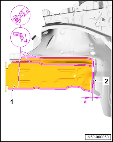
– Remove any foam residue -3-.
– Mark parting cut -2- on front longitudinal member -1- in accordance with dimension -a-, and make parting cut in a straight line.
♦ Dimension -a- = 55 mm
– Separate original joint.
– Remove front longitudinal member -1-.

– Remove remaining material on original joint -1-.
– Remove remaining material.
– Sand bonding and welding surfaces down to bare metal, and clean them.
Installing
Replacement parts
♦ For allocation of 2-pack body adhesive, see → Electronic parts catalogue (ETKA)
Important
● New parts must be adapted and attached with the vehicle standing on the straightening bracket set.
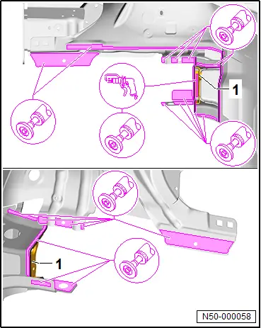
– Sand bonding and welding surfaces on new part -1- down to bare metal, and clean them.

– Transfer separating cut -2- to new part -1-, and cut in a straight line.
– Transfer separating cut -3- to new part -4-, and cut in a straight line.
– Drill 8 mm diameter holes for SG plug weld seam in new part -6-.
– Grind bonding surfaces and welding surfaces on new part -1- to -7- down to bare metal and clean.
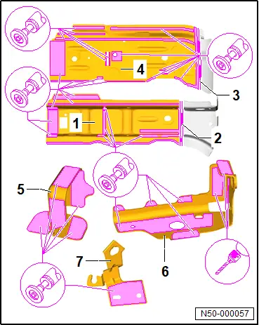
Important
● Exact position of new parts must be carried over from old part.
– Grind welding surfaces back to bare metal and clean.
– Apply 2-component body adhesive to entire surface.
– Adapt new part -2- to new part -1- via hole, and fix in position.
– Adapt new part -4- to new part -3-, and fix in position.
– Weld in new part -1- and -4-, RP spot weld seam.
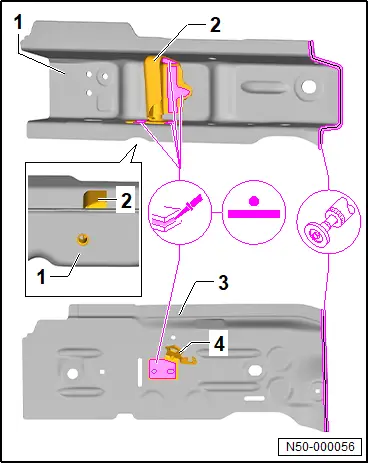
– Apply 2-component body adhesive to entire surface.
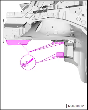
– Adapt new part -1- to fit, and fix it in position.
– Check fit with attachments.
– Weld in new part -1-, SG continuous weld seam and RP spot weld seam.

– Apply 2-component body adhesive to entire surface.
– Adapt new part -1- to fit via hole, and fix it in position.
– Check fit with attachments.
– Weld in new part -1- (SG plug weld seam and RP spot weld seam).
– Prepare moulded foam insert -2- for installation and insert.
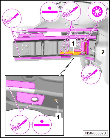
– Adapt new part -1- to fit, and fix it in position.
– Check fit with attachments.
– Weld in new part -1-, SG continuous weld seam and RP spot weld seam.

– Apply 2-component body adhesive to entire surface.
– Adapt new part -1- to fit, and fix it in position.
– Check fit with attachments.
– Weld in new part -1- (RP spot weld seam).
– Install battery tray → Rep. gr.50; Renewing battery tray.

Vehicles with studs.
All vehicles (continued)
– Renew studs.
Renewing front right longitudinal member (part section)
Renewing front right longitudinal member (part section)
 WARNING
Gases/ vapours hazardous to health are generated when welding, soldering or cutting using tools which produce sparks in foam-treated areas.
– Do not weld, solder or cut closer than 15 mm to moulded foam inserts.
– Use an extraction system during work.
 NOTICE
If separating cuts are made too deep, underlying reinforcement could be damaged.
– Only make separating cuts with body saw.
– Rewelding of reinforcements is not permitted due to safety reasons.
NOTICE
If welds are positioned too far on outside, strength could be impaired
– RP weld points must be placed as far as possible from outer edge of welding flange.
NOTICE
Strength could be impaired if continuous seam is changed
– SG continuous weld seam must not be reworked (ground or smoothed).
NOTICE
If adhesive is applied prematurely, bond could be impaired
– New part must be welded in within 90 minutes.
Observe safety information → Rep. gr.00; Safety information
Only tools and workshop equipment authorised by Volkswagen AG may be used → Rep. gr.00; Tools.
Removing
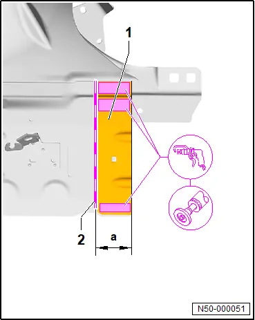
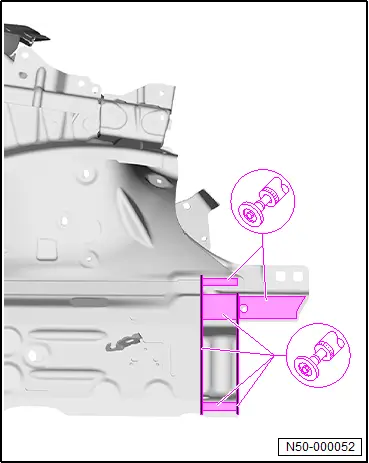
– Mark separating cut -2- all around on front longitudinal member -1- in accordance with dimension -a-, and cut in a straight line.
♦ Dimension -a- = 83 mm
– Separate original joint.
– Remove longitudinal member part section -1-.

– Mark parting cut -2- on front longitudinal member -1- in accordance with dimension -a-, and make parting cut in a straight line.
♦ Dimension -a- = 40 mm
– Separate original joint.
– Remove remainder of longitudinal member -1-.
– Remove remaining material.
– Completely remove adhesive residue.
– Sand bonding and welding surfaces down to bare metal, and clean them.
Installing
Replacement parts
♦ For allocation of 2-pack body adhesive, see → Electronic parts catalogue (ETKA)
Important
● New parts must be adapted and attached with the vehicle standing on the straightening bracket set.
– Sand bonding and welding surfaces on new part -1- down to bare metal, and clean them.

– Transfer separating cut -2- to new part -1-, and cut in a straight line.
– Transfer separating cut -3- to new part -4-, and cut in a straight line.
– Sand bonding and welding surfaces down to bare metal, and clean them.
– Apply 2-component body adhesive over entire area of RP spot weld seam.
– Adapt new part -1- and -2- to fit, and fix in position.
– Check fit with attachments.
– Weld in new part -1- and -2-, RP spot weld seam and SG continuous weld seam.
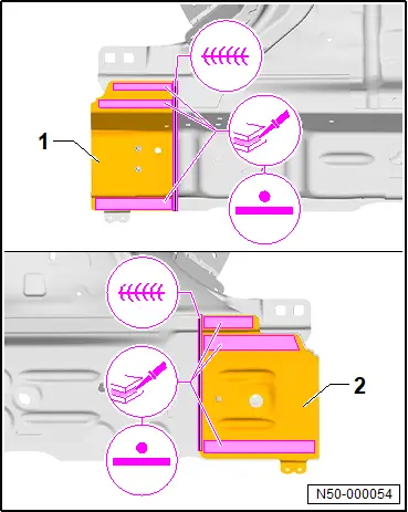
– Apply 2-component body adhesive to entire surface.
– Adapt new part -1- to fit, and fix it in position.
– Check fit with attachments.
– Weld in new part -1- (RP spot weld seam).
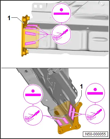
Vehicles with studs.
All vehicles (continued)
– Renew studs.
Renewing front right longitudinal member, part section (second separating cut)
Renewing front right longitudinal member, part section (second separating cut)
 WARNING
Gases/ vapours hazardous to health are generated when welding, soldering or cutting using tools which produce sparks in foam-treated areas.
– Do not weld, solder or cut closer than 15 mm to moulded foam inserts.
– Use an extraction system during work.
 NOTICE
If separating cuts are made too deep, underlying reinforcement could be damaged.
– Only make separating cuts with body saw.
– Rewelding of reinforcements is not permitted due to safety reasons.
NOTICE
If welds are positioned too far on outside, strength could be impaired
– RP weld points must be placed as far as possible from outer edge of welding flange.
NOTICE
Strength could be impaired if continuous seam is changed
– SG continuous weld seam must not be reworked (ground or smoothed).
NOTICE
If adhesive is applied prematurely, bond could be impaired
– New part must be welded in within 90 minutes.
Observe safety information → Rep. gr.00; Safety information
Only tools and workshop equipment authorised by Volkswagen AG may be used → Rep. gr.00; Tools.
Removing
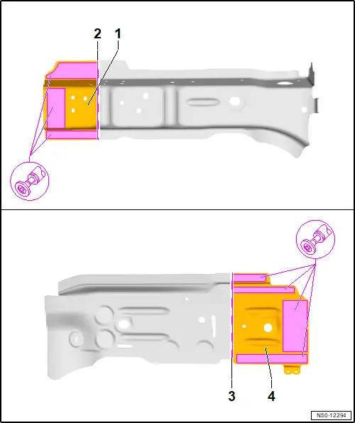
– Mark separating cut -2- on cover plate for front longitudinal member -1- in accordance with dimension -a- and cut in a straight line.
♦ Dimension -a- = 15 mm
– Separate original joint.
– Remove front longitudinal member cover plate -1-.
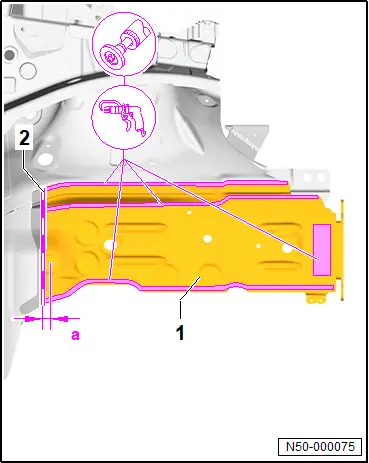
– Remove any foam residue -3-.
– Mark parting cut -2- on front longitudinal member -1- in accordance with dimension -a-, and make parting cut in a straight line.
♦ Dimension -a- = 55 mm
– Separate original joint.
– Remove front longitudinal member -1-.
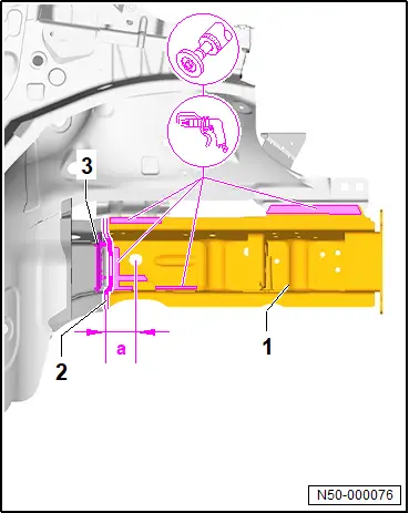
– Separate original joint on remaining material -1-.
– Remove remaining material.
– Sand bonding and welding surfaces down to bare metal, and clean them.

Installing
Replacement parts
♦ For allocation of 2-pack body adhesive, see → Electronic parts catalogue (ETKA)
Important
● New parts must be adapted and attached with the vehicle standing on the straightening bracket set.
– Sand bonding and welding surfaces on new part -1- down to bare metal, and clean them.
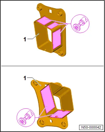
– Transfer separating cut -2- to new part -1-, and cut in a straight line.
– Transfer separating cut -4- to new part -3-, and cut in a straight line.
– Drill 8 mm diameter holes for SG plug weld seam in new part -8-.
– Grind bonding surfaces and welding surfaces on new part -1- to -8- down to bare metal and clean.

Important
● Exact position of new parts must be carried over from old part.
– Grind welding surfaces back to bare metal and clean.
– Apply 2-component body adhesive to entire surface.
– Adapt new part -2- to new part -1- via hole, and fix in position.
– Adapt new part -3- to new part -1-, and fix in position.
– Adapt new part -5- to new part -4-, and fix in position.
– Weld in new part -1- and -5-, RP spot weld seam.
– Apply 2-component body adhesive to entire surface.
– Adapt new part -1- to fit, and fix it in position.
– Check fit with attachments.
– Weld in new part -1-, SG continuous weld seam and RP spot weld seam.

– Apply 2-component body adhesive to entire surface.
– Adapt new part -1- to fit via hole, and fix it in position.
– Check fit with attachments.
– Weld in new part -1- (SG plug weld seam and RP spot weld seam).
– Prepare moulded foam insert -2- for installation and insert.

– Adapt new part -1- to fit, and fix it in position.
– Check fit with attachments.
– Weld in new part -1-, SG continuous weld seam and RP spot weld seam.
– Apply 2-component body adhesive to entire surface.
– Adapt new part -1- to fit, and fix it in position.
– Check fit with attachments.
– Weld in new part -1- (RP spot weld seam).
Vehicles with studs.
All vehicles (continued)
– Renew studs.
Renewing upper longitudinal member
Renewing upper longitudinal member
 WARNING
Gases/ vapours hazardous to health are generated when welding, soldering or cutting using tools which produce sparks in foam-treated areas.
– Do not weld, solder or cut closer than 15 mm to moulded foam inserts.
– Use an extraction system during work.
 NOTICE
If separating cuts are made too deep, underlying reinforcement could be damaged.
– Only make separating cuts with body saw.
– Rewelding of reinforcements is not permitted due to safety reasons.
NOTICE
If welds are positioned too far on outside, strength could be impaired
– RP weld points must be placed as far as possible from outer edge of welding flange.
NOTICE
If adhesive is applied prematurely, bond could be impaired
– New part must be welded in within 90 minutes.
Observe safety information → Rep. gr.00; Safety information
Only tools and workshop equipment authorised by Volkswagen AG may be used → Rep. gr.00; Tools.
Removal and installation are described for left side of vehicle as an example.
Removing
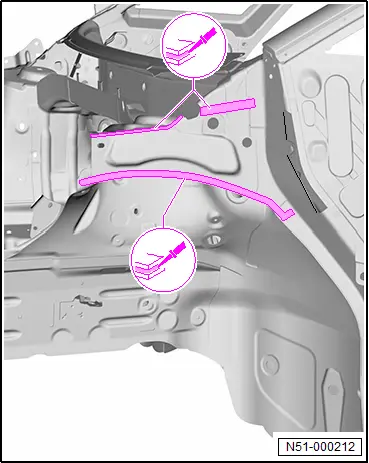
– Make separating cut -2- on upper longitudinal member -1- as shown.
– Separate original joint.
– Remove upper longitudinal member -1-.

– Remove remaining material.
– Completely remove adhesive residue.
– Sand bonding and welding surfaces down to bare metal, and clean them.

Installing
Replacement parts
♦ For allocation of 2-pack body adhesive, see → Electronic parts catalogue (ETKA)
Important
● New parts must be adapted and attached with the vehicle standing on the straightening bracket set.
– Transfer separating cut -2- to new part -1- and cut.
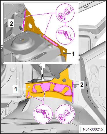
– Drill 8 mm diameter holes for SG plug weld seam in new part -1-.
– Sand bonding and welding surfaces down to bare metal, and clean them.
– Apply 2-component body adhesive to entire surface.
– Adapt new part -1- to fit, and fix it in position.
– Check fit with attachments.
– Weld in new part -1- (SG plug weld seam and RP spot weld seam).
– Weld parting cut, SG stepped weld seam.

Renewing upper inner longitudinal member
Renewing upper inner longitudinal member
 WARNING
Gases/ vapours hazardous to health are generated when welding, soldering or cutting using tools which produce sparks in foam-treated areas.
– Do not weld, solder or cut closer than 15 mm to moulded foam inserts.
– Use an extraction system during work.
 NOTICE
Do not damage underlying reinforcements.
Rewelding of reinforcement is not permitted due to safety reasons.
NOTICE
If welds are positioned too far on outside, strength could be impaired
– RP weld points must be placed as far as possible from outer edge of welding flange.
NOTICE
If adhesive is applied prematurely, bond could be impaired
– New part must be welded in within 90 minutes.
Observe safety information → Rep. gr.00; Safety information
Only tools and workshop equipment authorised by Volkswagen AG may be used → Rep. gr.00; Tools.
Removal and installation are described for left side of vehicle as an example.
Removing
Upper longitudinal member already removed → Rep. gr.50; Renewing upper longitudinal member
– Make separating cut -2- on upper inner longitudinal member -1- as shown.
– Separate original joint.
– Remove upper inner longitudinal member -1-.
– Remove remaining material.
– Completely remove adhesive residue.
– Sand bonding and welding surfaces down to bare metal, and clean them.

Installing
Replacement parts
♦ For allocation of 2-pack body adhesive, see → Electronic parts catalogue (ETKA)
Important
● New parts must be adapted and attached with the vehicle standing on the straightening bracket set.
– Transfer separating cut -2- to new part -1- and cut.
– Sand bonding and welding surfaces on new part -1- down to bare metal, and clean them.
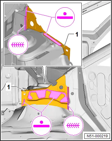
– Apply 2-component body adhesive to entire surface.
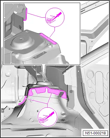
– Adapt new part -1- to fit, and fix it in position.
– Check fit with attachments.
– Weld in new part -1-, SG continuous weld seam and RP spot weld seam.
– Install upper part of longitudinal member → Rep. gr.50; Renewing upper part of longitudinal member.
Assembly overview - battery tray
Assembly overview - battery tray

1 - Front battery tray
❏ → Chapter „Renewing battery tray“
2 - Rear battery tray
❏ → Chapter „Renewing battery tray“
3 - Bonded areas
❏ Cannot be restored
Renewing battery tray
Renewing battery tray
 WARNING
Gases/ vapours hazardous to health are generated when welding, soldering or cutting using tools which produce sparks in foam-treated areas.
– Do not weld, solder or cut closer than 15 mm to moulded foam inserts.
– Use an extraction system during work.
Observe safety information → Rep. gr.00; Safety information
Only tools and workshop equipment authorised by Volkswagen AG may be used → Rep. gr.00; Tools.
Removing
– Separate original joint.
– Remove front battery tray -1-.
– Remove rear battery tray -2-.
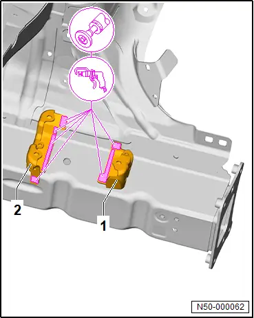
– Remove remaining material.
– Completely remove adhesive residue.
– Grind welding surfaces back to bare metal and clean.

Installing
– Drill holes (8 mm in diameter) for SG plug weld seam into new part -1- and -2-.
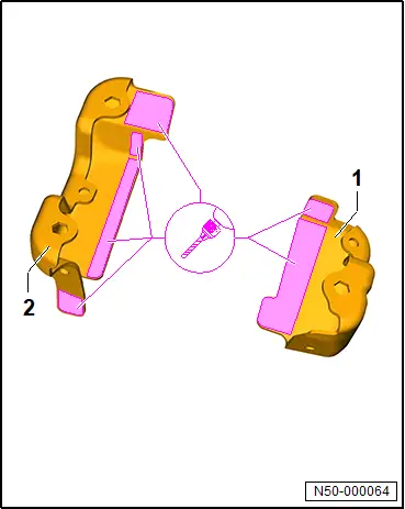
– Adapt new part -1- and -2- to fit, and fix in position.
– Check fit with attachments.
– Weld in new part -1- and -2-, SG plug weld seam.