Brake, brake mechanics. Front brake

In this manual: Brake, brake mechanics. Front brake
Technical data. Panel gaps - front — 1Body front. Lock carrier — 1Body front. Wings — 1Body front. Bulkhead — 1Bonnet, flaps, cab, central locking. Bonnet — 1Bonnet, flaps, cab, central locking. Rear lid — 1Bonnet, flaps, cab, central locking. Charging flap unit — 1Front door, central locking. Door — 1Front door, central locking. Door components — 1Front door, central locking. Central locking — 1Rear door,sliding door,wing doors,central locking. Door — 1Rear door,sliding door,wing doors,central locking. Door components — 1Sliding roof. Sliding sunroof — 1Bumper. Bumper, front — 1Bumper. Bumper, rear — 1Glazing & window mechanism. Repair notes — 1Glazing & window mechanism. Windscreen — 1Glazing & window mechanism. Rear windscreen — 1Glazing & window mechanism. Side windows — 1Glazing & window mechanism. Door windows — 1Exterior equipment. Spoiler — 1Exterior equipment. Mouldings, trims, extensions — 1Exterior equipment. Underbody cladding — 1Exterior equipment. Roof moulding and roof railing — 1Exterior equipment. Exterior mirror — 1Exterior equipment. Wheel housing liner — 1Exterior equipment. Lettering and emblems — 1Exterior equipment. Bicycle carrier — 1Exterior equipment. Trim film and protective film — 1Interior equipment. Compartments & covers — 1Interior equipment. Equipment — 1Interior equipment. Centre console — 1Interior equipment. Front centre armrest — 1Interior equipment. Interior mirror — 1Passenger protection. Seat belts — 1Passenger protection. Child seat anchors — 1Passenger protection. Airbag system — 1Passenger protection. Airbag control unit — 1Passenger protection. Front airbag, driver side — 1Passenger protection. Front passenger airbag — 1Passenger protection. Side airbags — 1Passenger protection. Curtain airbags — 1Passenger protection. Airbag crash sensors — 1Passenger protection. Seat occupied recognition — 1Trim, noise insulation. Front door trims — 1Trim, noise insulation. Rear door trims — 1Trim, noise insulation. Dash panel — 1Trim, noise insulation. Central tube for dash panel — 1Trim, noise insulation. Interior trims — 1Trim, noise insulation. Roof trims — 1Trim, noise insulation. Luggage compartment trims — 1Seat frames. Overview of seat variants — 1Seat frames. Front seats — 1Seat frames. Rear seats — 1Seat padding, covers. Front seat covers and padding — 1Seat padding, covers. Rear seat covers and padding — 1Vehicle-specific paintwork information. Explanation of symbols — 1Vehicle-specific paintwork information. Paintwork structure — 1Vehicle-specific paintwork information. Areas exposed to stone chipping — 1Vehicle-specific paintwork information. Masked sectors — 1Vehicle-specific paintwork information. Seam sealing — 1Vehicle-specific paintwork information. Underseal — 1Vehicle-specific paintwork information. Cavity sealing — 1Vehicle-specific paintwork information. Contrasting colours — 1Vehicle-specific paintwork information. Paintwork repair — 1Technical data. Acoustic considerations during vehicle development — 1Technical data. General procedure for identifying noises — 1Technical data. Volkswagen equipment for localising noises — 1Technical data. Borescope VAS 6748A — 1Technical data. Causes — 1Technical data. Locating water ingress — 1Technical data. Attachments — 1Technical data. Vehicle identification data — 1Technical data. Safety information — 1Technical data. Body parts and materials — 1Technical data. Alignment jig — 1Body front. Longitudinal member cross panel — 1Body front. Longitudinal member — 1Body front. Front wheel housing — 1Body centre, roof, frame. Roof — 1Body centre, roof, frame. A-pillar — 1Body centre, roof, frame. B-pillar — 1Body centre, roof, frame. Side member — 1Body, rear. Rear cross member — 1Body, rear. Rear cross panel — 1Body, rear. Luggage compartment floor — 1Body, rear. Rear longitudinal member — 1Body, rear. Side panel — 1Body, rear. Rear wheel housing — 1General information, Body. Basic information on body repairs — 1General information, Body. Explanation of symbols — 1General information, Body. Overview of materials used — 1General information, Body. Joining and separating techniques — 1General information, Body. Surface repair — 1General information, Body. Corrosion protection — 1General information, Body. Noise insulation — 1General information, Body. Plastic repair — 1General information, Body. Welding plastic attachments — 1General information, Body. General notes – windows — 1General information, Body. Glass repair — 1General information, Body. Use of adhesives — 1General information, Body. Self-adhesive components — 1General information, Body. Noises — 1General information, Body. Preparing for disposal — 1General information, Body. Leaks — 1General information, paint. Safety information — 1General information, paint. General information — 1Genuine products. Filler — 1Genuine products. Priming metal — 1Genuine products. Priming plastic materials — 1Genuine products. Surfacer — 1Genuine products. 2-pack top coats — 1Repair painting work. Paint finish – decorative strips and films — 1Repair painting work. Tips and tricks — 1Air conditioner. Overview of fitting locations — 1Air conditioner. Refrigerant circuit — 1Air conditioner. Valve unit of heat pump — 1Air conditioner. Air conditioner compressor — 1Air conditioner. Control motors — 1Air conditioner. Front heater and air conditioning unit — 1Air conditioner. Air duct — 1Air conditioner. Coolant circuit — 1Air conditioner. Other controlling and regulating components — 1Air conditioner. Air quality improvement system — 11-speed gearbox 0MH, rear, EQ310. Technical data — 11-speed gearbox 0MH, rear, EQ310. Gearbox mechanics,operation, construction,diff — 11-speed gearbox 0MH, rear, EQ310. Final drive, differential, differential lock — 1General information. High voltage — 1Electric drive EIP220, EIA200, EIA210. Technical data — 1Electric drive EIP220, EIA200, EIA210. Engine assy,cylinder block,crankcase — 1Electric drive EIP220, EIA200, EIA210. Engine cooling — 1Electric drive. High-voltage components, charging unit and voltage converter — 1Electric drive. Warning stickers — 1Electric drive. High-voltage battery unit, edge of upper part of battery housing without wax — 1Electric drive. High-voltage battery unit, edge of upper part of battery housing with wax — 1Electric drive. Power and control electronics for electric drive — 1Electric drive. Electric drive motor — 1Electric drive. Motor control unit — 1Electric drive. De-energising high-voltage system — 1Electric drive. Re-energise high-voltage system — 1Electric drive. Potential equalisation lines — 1Electric drive. Charging socket, with charging cable — 1Electric drive. Charging socket, with separate charging cable — 1Electric drive. Charging unit for high-voltage battery — 1Electric drive. Charging unit for high-voltage battery, with integrated voltage converter — 1Electric drive. Vehicle noise & engine sound — 1Electric drive. Accelerator pedal — 1Electric drive. Voltage converter — 1Electric drive. High-voltage cables, all-wheel drive — 1Electric drive. High-voltage cables, rear-wheel drive — 1Front suspension, drive shafts. Front axle — 1Front suspension, drive shafts. Subframe — 1Front suspension, drive shafts. Suspension strut, upper suspension link — 1Front suspension, drive shafts. Lower suspension link, swivel joint — 1Front suspension, drive shafts. Wheel bearing — 1Front suspension, drive shafts. Anti-roll bar — 1Rear suspension, drive shaft. Rear axle — 1Rear suspension, drive shaft. Subframe — 1Rear suspension, drive shaft. Anti-roll bar — 1Rear suspension, drive shaft. Suspension link, track rod — 1Rear suspension, drive shaft. Suspension strut, shock absorber, spring — 1Rear suspension, drive shaft. Wheel bearing assembly, trailing arm — 1Rear suspension, drive shaft. Drive shaft — 1Self-levelling air spring system. Electronically controlled damping — 1Self-levelling air spring system. Vehicle level sender — 1Wheels, tyres. axle align. Wheel alignment — 1Wheels, tyres. axle align. Wheels, tyres — 1Steering. Steering wheel — 1Steering. Steering column — 1Steering. Steering rack — 1Brake system. Technical data — 1ABS, ADR, TCS, EDL, ESP. Overview of fitting locations — 1ABS, ADR, TCS, EDL, ESP. Control unit and hydraulic unit — 1ABS, ADR, TCS, EDL, ESP. Sensors — 1Brake, brake mechanics. Front brake — 1Brake, brake mechanics. Rear brake — 1Brake, brake mechanics. Parking brake — 1Brake, brake mechanics. Brake pedal — 1Brakes, hydraulics, regulator, servo. Brake servo and brake master cylinder — 1Brakes, hydraulics, regulator, servo. Hydraulic system — 1Wheels and Tyres Guide. Wheels, tyres. axle align — 1Wheels, tyres. axle align. Instructions on using the guide — 1Wheels, tyres. axle align. Legislative and technical conditions — 1Wheels, tyres. axle align. Wheel change — 1Wheels, tyres. axle align. Fitting tyre — 1Wheels, tyres. axle align. Wheel bolts — 1Wheels, tyres. axle align. Information on tyres — 1Wheels, tyres. axle align. Handling problems — 1Wheels, tyres. axle align. Evaluating tyres — 1Wheels, tyres. axle align. Tyre wear — 1Starter-current supply-CC. Battery — 1Instruments, GCI. Dash panel insert — 1Instruments, GCI. Horn — 1Windscreen wipewash system. Windscreen wiper system — 1Windscreen wipewash system. Windscreen washer system — 1Windscreen wipewash system. Rear window wiper system — 1Windscreen wipewash system. Rear window washer system — 1Lights, lamps, switches outside. LED headlight — 1Lights, lamps, switches outside. LED matrix headlight — 1Lights, lamps, switches outside. Tail lights — 1Lights, lamps, switches outside. Lights in exterior mirror — 1Lights, lamps, switches outside. Number plate light — 1Lights, lamps, switches outside. Entry and start authorisation system — 1Lights, lamps, switches outside. Steering column switch module — 1Lights, lamps, switches outside. Towing bracket — 1Lights, lamps, switches inside, anti-theft system. Lights — 1Lights, lamps, switches inside, anti-theft system. Controls — 1Lights, lamps, switches inside, anti-theft system. Anti-theft alarm system — 1Lights, lamps, switches inside, anti-theft system. Cigarette lighter, socket — 1Wiring. Relay carriers, fuse holders, electronics boxes — 1Wiring. Control units — 1Infotainment. Componentscontrol units — 1Infotainment. Multifunction steering wheel — 1Driver assist systems. Senders, sensors, control units — 1Driver assist systems. Adaptive cruise control — 1Driver assist systems. Reversing camera system — 1Driver assist systems. Front camera for driver assist systems — 1Driver assist systems. Overhead view camera — 1Electrical system. Starter-current supply-CC — 1Electrical system. Windscreen wipe and wash system — 1Wiring. Wires and lines — 1Wiring. Cleaning contact surfaces — 1
~8min read
060120180240300200148N·mlb·ft
Tightening torque found on this page
  • Assembly overview – front brake
  • Removing and installing brake caliper
  • Removing and installing brake pads
  • Removing and installing brake disc

Assembly overview – front brake

Assembly overview – front brake

The overview is shown for the left side of the vehicle as an example.

1 - Ribbed bolt

❏ Qty. 2

❏ 200 N·m

2 - Wheel bearing housing

❏ → Running gear, axles, steering; Rep. gr.42; Wheel bearing, trailing arm; Assembly overview – wheel bearing

3 - Brake pads

❏ Depending on equipment/version

❏ With front right brake pad wear sender -G35-

❏ Check thickness of brake linings → Booklet; Front and rear brake pads/linings: Checking thickness

❏ Renew on both sides.

❏ Wear limits

❏ → Rep. gr.00; Test and adjustment values → Rep. gr.46; Removing and installing brake pads

4 - Bolt

❏ Qty. 2

❏ Renew after removing

❏ 30 N·m

5 - Brake caliper

❏ Depending on equipment/version

❏ → Rep. gr.46; Removing and installing brake caliper

6 - Bleeder valve

❏ 11 N·m

7 - Dust cap

8 - Line for front right brake pad wear sender -G35-

9 - Brake carrier

10 - Pad retainer

❏ Renew after removing

11 - Brake disc

❏ Renew on both sides.

❏ Wear limits → Rep. gr.00; Test and adjustment values → Rep. gr.46; Removing and installing brake disc

12 - Torx bolt

❏ 8 N·m

13 - Torx bolt

❏ Qty. 3

❏ 12 N·m

14 - Cover plate

15 - Brake hose with banjo union and banjo bolt

❏ Ensure correct installation position

❏ Banjo bolt on brake caliper: 35 N·m

16 - Retaining clip

17 - Brake line

❏ 14 N·m

18 - Bolt

❏ 8 N·m

19 - Bracket

Removing and installing brake caliper

Removing and installing brake caliper

Special tools and workshop equipment required

♦ brake pedal actuator -V.A.G 1869/2-

♦ hook -VAS 281 007-

WARNING

Health hazard due to poisonous dust from brake system.

Risk of irreversibly deposited dust particles in the lungs. Risk of respiratory health problems.

– Do not blow out brake system with compressed air.

CAUTION

Brake pads that are reused.

Uneven braking efficiency.

– Mark brake pads when removing, and reinstall them in the same position.

NOTICE

Opened brake system.

Damage to brake system.

– Do not depress brake pedal during the procedure.

The work procedure applies only for renewal of the brake caliper.

Removal and installation are described for left side of vehicle as an example.

Removing

– Remove wheel → Running gear, axles, steering; Rep. gr.44; Wheels, tyres; Removing wheel.

Right side of vehicle

– Disconnect electrical connector of front right brake pad wear sender -G35-.

All vehicles (continued)

– Connect hose of bleeder bottle -1- to bleeder valve of brake caliper.

– Open bleeder valve.

– Fit brake pedal actuator -V.A.G 1869/2-.
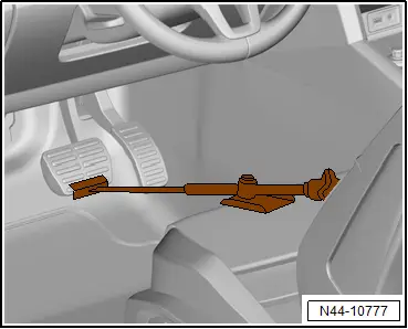
– Close bleed valve and remove bleed bottle.

– Unscrew brake hose.

– Unscrew bolts -2- while counterholding on guide pin -3-.

– Pull brake caliper off brake carrier -1-.

– Secure brake caliper -1- with hook -VAS 281 007- to prevent it from falling down.
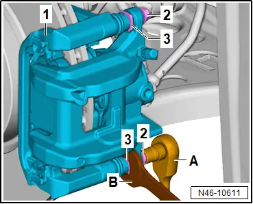
Installing

Important

● The piston is pressed back.

● The retaining springs of the brake pads are seated in the recesses in the brake carrier.

– Place brake caliper onto brake carrier.

– Secure brake caliper to brake carrier -1- with bolts -2- while counterholding on guide pin -3-.

– Screw brake hose into brake caliper, and tighten it.

– Remove brake pedal actuator -V.A.G 1869/2-.

Right side of vehicle

– Connect electrical connector of front right brake pad wear sender -G35-.

All vehicles (continued)

– → Rep. gr.47; Bleed hydraulic system.

– Install wheel → Running gear, axles, steering; Rep. gr.44; Wheels, tyres; Installing wheel.

Firmly depress brake pedal several times with vehicle stationary so that the brake pads/linings are properly seated in their normal operating position.

– Check brake fluid level.

Important

● The brake fluid level must be between “Min.” -2- and “Max.” -1-.

Continued

Tightening torques

♦ → Rep. gr.46; Assembly overview – front brake

Removing and installing brake pads

Removing and installing brake pads

Special tools and workshop equipment required

♦ Piston resetting appliance -T10145-

♦ hook -VAS 281 007-

WARNING

Health hazard due to poisonous dust from brake system.

Risk of irreversibly deposited dust particles in the lungs. Risk of respiratory health problems.

– Do not blow out brake system with compressed air.

NOTICE

Opened brake system.

Damage to brake system.

– Do not depress brake pedal during the procedure.

Removing

Removal and installation are described for left side of vehicle as an example.

– → Running gear, axles, steering; Rep. gr.44; Wheels, tyres; Removing wheel

Right side of vehicle

– Disconnect electrical connector of front right brake pad wear sender -G35-.

All vehicles (continued)

– Unscrew bolts -2- from brake carrier -1-. Counterhold on guide pin -3- when doing this.

– Remove brake caliper -1-.

– Secure brake caliper -1- with hook -VAS 281 007- to prevent it from falling down.

– Use a screwdriver -A- to lever off brake pad retaining springs -arrows-.

Important

● Do not bend brake pad retaining springs when doing this.
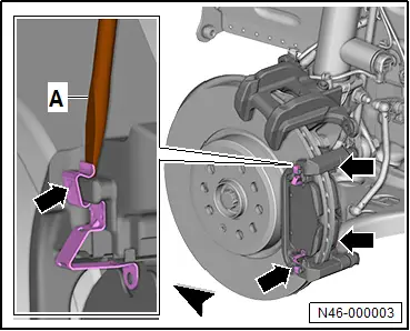
– Mark used brake pads when removing, and reinstall them in the same position.

– Turn brake pad -1- in direction of -arrow A-, and remove it in direction of -arrow B-.
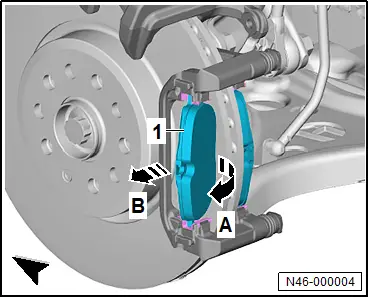
– Use a screwdriver -A- to lever off pad retainers -1- at positions marked with -arrows-.

– Thoroughly clean contact surfaces of brake pads on brake carrier using suitable workshop means, and remove corrosion.

CAUTION

Risk of injury from chemical cleaning agents. Chemical cleaning agents can be highly flammable and can cause eye and skin irritation.

– Wear safety goggles, safety gloves and a respirator mask.

– Observe safety data sheet and instructions for use of the cleaning agent.

– Clean brake caliper.

Important

● Use only commercially available methylated spirits for cleaning the brake caliper.

Installing

Important

● Before pushing the brake piston back into the cylinder using the piston resetting appliance -T10145-, brake fluid must be extracted from the brake fluid reservoir so that no brake fluid that has been refilled in the meantime can drain out.

For a better view, the following work procedure is shown with the brake caliper removed.

– Press back piston with piston resetting appliance -T10145- -A-.

– Press pad retainers -arrows- into brake carrier.

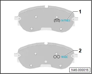
For directional brake pads

– Install directional brake pads marked with “OUTSIDE”-1- on the outer side and those marked with “INSIDE”-2- on the inner side.
All vehicles (continued)

Important

● Bake pads must be renewed on both sides of axle.

– Push brake pad -1- in direction of -arrow A- against resistance of brake pad retaining springs -2- into recess in brake carrier.

– Simultaneously, push brake pad -1- in direction of -arrow B- into recess in brake carrier and against brake disc (direction of -arrow C-).
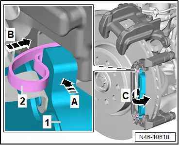
– Press brake pad retaining springs -arrows- onto brake carrier.

– Make sure that all brake pad retaining springs -arrows- are firmly seated.

– Place brake caliper onto brake carrier.

– Secure brake caliper to brake carrier -1- using new self-locking bolts -2- while counterholding on guide pin -3-.

Right side of vehicle

– Connect electrical connector of front right brake pad wear sender -G35-.

All vehicles (continued)

– → Running gear, axles, steering; Rep. gr.44; Wheels, tyres; Installing wheel.

– Firmly depress brake pedal several times with vehicle stationary so that the brake pads/linings are properly seated in their normal operating position.

– Check brake fluid level.

Important

● Brake fluid level must be between “MIN.” -2- and “MAX.” -1-.

– Ensure that brakes work properly before the vehicle is driven.

Tightening torques

♦ → Rep. gr.46; Assembly overview – front brake

Removing and installing brake disc

Removing and installing brake disc

Removing

Removal and installation are described for the left side of vehicle as an example.

– Remove brake pads → Rep. gr.46; Removing and installing brake pads.

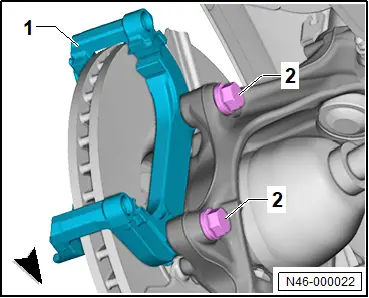
– Unscrew bolts -2-, and remove brake carrier -1-.
– Unscrew bolt -2-, and hold brake disc -1- when doing this.

– Remove brake disc -1-.
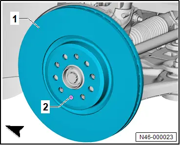
– Thoroughly clean contact surface of brake disc and wheel hub. Remove corrosion with suitable workshop equipment.

– Clean brake discs.

Important

● Use only commercially available methylated spirits to clean brake discs.

Installing

Install in reverse order of removal, observing the following:

Important

● Bake discs must be renewed on both sides of axle.

Tightening torques

♦ → Rep. gr.46; Assembly overview – front brake