Seat frames. Rear seats
- Assembly overview – bench seat/individual seats
- Assembly overview ? rear seat backrest
- Assembly overview ? locking mechanism
- Assembly overview – centre armrest
- Removing and installing bench seat/individual seats
- Removing and installing seat pan
- Removing and installing head restraint
- Removing and installing head restraint guide
- Removing and installing rear seat backrest
- Removing and installing back panel trim
- Removing and installing trim for locking mechanism
- Removing and installing locking mechanism for rear seat backrest
- Removing and installing trim frame for load-through hatch
- Removing and installing flap for load-through hatch
- Removing and installing centre armrest
Assembly overview – bench seat/individual seats
Assembly overview – bench seat/individual seats
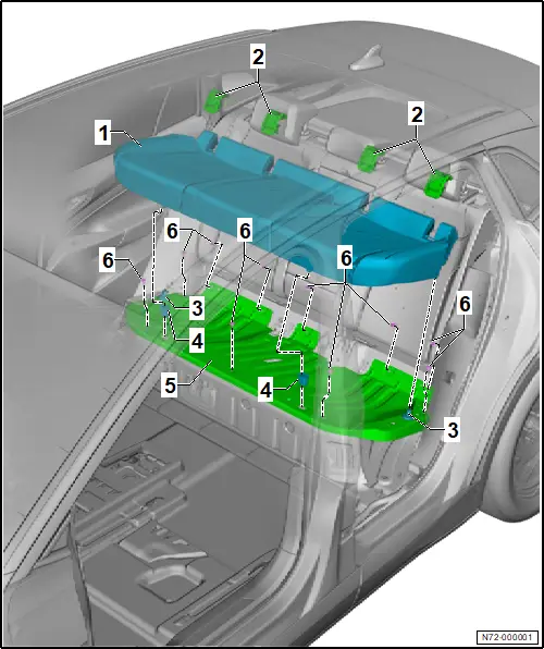
1 - Bench seat
❏ Depending on equipment/version
❏ → Rep. gr.72; Removing and installing bench seat/individual seats
2 - Child seat anchor guide in bench seat
❏ Qty. 4
❏ → Rep. gr.74; Removing and installing cover and padding of rear bench seat
3 - Arrester
❏ Qty. 2
4 - Grommet
❏ Qty. 2
❏ Renew after removing
5 - Seat pan
❏ → Rep. gr.72; Removing and installing seat pan
6 - Bolt
❏ Qty. 10
❏ → Fig.
❏ 8 N·m
Specified torque and tightening sequence
 StageBoltsSpecified torque1 -3- 8 Nm2 -1- 8 N·m
Assembly overview ? rear seat backrest
Assembly overview ? rear seat backrest
The overview is shown for the rear seat backrest (2/3) as an example.

1 - Rear seat backrest
❏ → Rep. gr.72; Removing and installing rear seat backrest
2 - Locking mechanism for rear seat backrest
❏ → Rep. gr.72; Assembly overview – locking mechanism
❏ → Rep. gr.72; Removing and installing locking mechanism for rear seat backrest
3 - Outer head restraint
❏ → Rep. gr.72; Removing and installing head restraint
4 - Rear belt guide
❏ Depending on equipment/version
❏ → Rep. gr.69; Removing and installing rear belt guide
5 - Centre head restraint
❏ → Rep. gr.72; Removing and installing head restraint
6 - Head restraint guide
❏ → Rep. gr.72; Removing and installing head restraint guide
7 - Flap for load-through hatch
❏ Depending on equipment/version
❏ → Rep. gr.72; Removing and installing flap for load-through hatch
8 - Inner pivot pin
❏ 13,5 N·m
9 - Locking bar
❏ → Rep. gr.72; Removing and installing rear seat backrest
10 - Bolt
❏ 9 N·m
11 - Cover
❏ → Rep. gr.72; Removing and installing rear seat backrest
12 - Centre mount
13 - Centre armrest
❏ Depending on equipment/version
❏ → Rep. gr.72; Assembly overview – centre armrest
❏ → Rep. gr.72; Removing and installing centre armrest
14 - Rear centre three-point seat belt
❏ Depending on equipment/version
❏ → Rep. gr.69; Removing and installing rear three-point seat belt
15 - Outer support pin
Assembly overview ? locking mechanism
Assembly overview ? locking mechanism
The overview is shown for the left side of vehicle as an example.
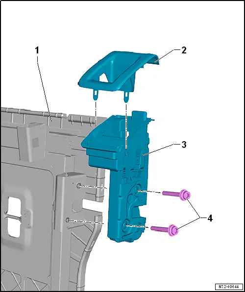
1 - Frame, rear seat backrest
2 - Locking mechanism trim
❏ → Rep. gr.72; Removing and installing locking mechanism trim
3 - Locking mechanism for rear seat backrest
❏ → Rep. gr.72; Removing and installing locking mechanism for rear seat backrest
4 - Bolt
❏ qty. 2
❏ 23 N·m
Assembly overview – centre armrest
Assembly overview – centre armrest
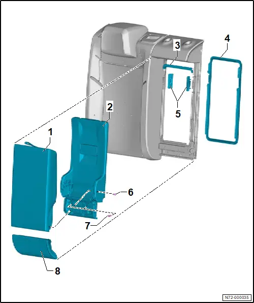
1 - Centre armrest
❏ → Rep. gr.72; Removing and installing centre armrest
2 - Flap for load-through hatch
❏ → Rep. gr.72; Removing and installing flap for load-through hatch
3 - Stop strip
❏ → Rep. gr.72; Removing and installing trim frame for load-through hatch
4 - Trim frame for load-through hatch
❏ → Rep. gr.72; Removing and installing trim frame for load-through hatch
5 - Flap catch trim
❏ Qty. 2
❏ → Rep. gr.72; Removing and installing trim frame for load-through hatch
6 - Bolt
❏ Self-tapping
❏ Qty. 2
❏ Renew after removing
❏ 12 N·m
7 - Bolt
❏ Qty. 2
❏ 8 N·m
8 - Intermediate padding
❏ → Rep. gr.74; Removing and installing intermediate padding, backrest with load-through hatch
Removing and installing bench seat/individual seats
Removing and installing bench seat/individual seats
Special tools and workshop equipment required
♦ removal tool -T40445-
Removing
– Move front seats to foremost position.
– Remove child seat anchor guides → Rep. gr.74; Removing and installing cover and padding of rear bench seat.
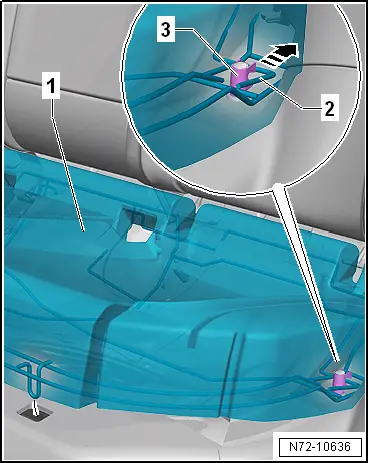
– Push in removal tool -T40445- to stop in area of wire hook -2- between bench seat -1- and bracket.
– Push removal tool -T40445- upwards and carefully lever bench seat -1- in direction of -arrow A- out of grommet -3-.
– Repeat procedure on other side -arrow B-.
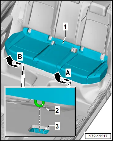
– Slightly raise bench seat -1- at front, and push wire frame -2- in direction of -arrow- out of arresters -3-.
– Disconnect electrical connector.
– Remove bench seat -1-.
Installing
Install in reverse order of removal, observing the following:
– Check body aperture -arrow- for deformation.
Note
Slight remaining deformations are permissible.
– Repair any sheet metal deformations using a plastic hammer.
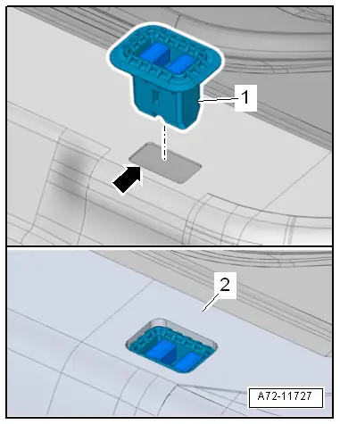
– Raise floor covering -2-, and press new grommets -1- into body apertures -arrow- until they engage audibly.
– Arrange floor covering -2- around grommet taking care not to cover the grommet.
– Before installing the bench seat, check if the wire frame is aligned properly in the area indicated by -arrows-.
– If applicable, bend back deformed wire frame until it is properly aligned again.
Note
Make sure that the wire hooks engage properly.
– Insert bench seat, and firmly press wire hooks into grommets.

Removing and installing seat pan
Removing and installing seat pan
Removing
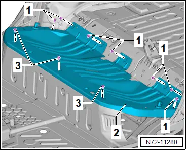
– Remove bench seat → Rep. gr.72; Removing and installing bench seat/individual seats.
– Remove rear sill panel moulding → Rep. gr.70; Removing and installing rear sill panel moulding
– Fold floor covering in area of seat pan towards front.
– Unscrew bolts -1- and -3-.
– Remove seat pan -2-.
Installing
Install in reverse order of removal, observing the following:
Tightening torques
♦ → Rep. gr.72; Assembly overview – bench seat/individual seats
Removing and installing head restraint
Removing and installing head restraint
Removing
– Release rear seat backrest, and fold it forwards slightly.
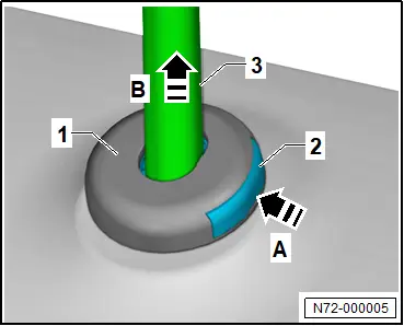
– Press height adjustment release button -2- on head restraint guide -1- in direction of -arrow A-, and hold it there.
– Move head restraint -3- as far as stop upwards -arrow B-.
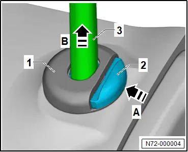
– Press release button -2- on head restraint guide -1- in direction of -arrow A-, and hold it there.
– Pull head restraint -3- in direction of -arrow B- out of head restraint guide -1-, and remove it.
Installing
Install in reverse order of removal.
Removing and installing head restraint guide
Removing and installing head restraint guide
Removing
Note
3 commercially available screwdrivers with a blade height of 0.4 mm and a blade width of 8 mm are required for removal.
– Remove head restraint → Rep. gr.72; Removing and installing head restraint.
– Push cover and padding -1- on outer side slightly downwards.
Note
Position 2 screwdrivers next to locking devices so that flat side of screwdriver blade rests against locking device.
– Insert a screwdriver on each side of head restraint channel -4-, and push it in as far as locking device -3-.
– Turn both screwdrivers 90° in direction of -arrow B-, and release locking devices -3- in direction of -arrow A-.
– Using an additional screwdriver, lever head restraint guide -2- off head restraint channel -4-.

Installing
Install in reverse order of removal.
Removing and installing rear seat backrest
Removing and installing rear seat backrest
Removing
Removal and installation is described for the rear seat backrest (2/3).
– Remove rear shelf.
Rear seat backrest (2/3)
– Remove rear right belt buckle → Rep. gr.69; Removing and installing rear right belt buckle.
– Fold down flap for load-through hatch.
All vehicles (continued)
Note
For reasons of clarity, the left rear seat backrest (1/3) is not shown in illustration.
– Pull cover -1- off centre mount -2-.

– Unscrew bolt -2-.
– Fold locking bar -1- in direction of -arrow A-, detach it from centre mount -arrow B-, and remove it.

– Lift out rear seat backrest -2- at inner pivot pin -3- in direction of -arrow A-, and pull it out at outer pivot pins -1- in direction of -arrow B-.
– Remove rear seat backrest -2-.

Installing
Install in reverse order of removal, observing the following:
– Push rear seat backrest -2- in opposite direction of -arrow B- onto outer pivot pin -1-.
– Position inner pivot pin -3- in centre mount -4-.
Tightening torques
♦ → Rep. gr.72; Assembly overview - rear seat backrest
Removing and installing back panel trim
Removing and installing back panel trim
Special tools and workshop equipment required
♦ Hot air blower -V.A.G 1416-
Removing
– Remove head restraint → Rep. gr.72; Removing and installing head restraint.
– Fold rear seat backrest towards front.
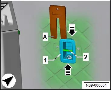
– Using commercially available plastic wedge -A-, release locking devices in direction of -arrow-, and lever off child seat anchor cover in rear seat backrest -1- upwards.
Note
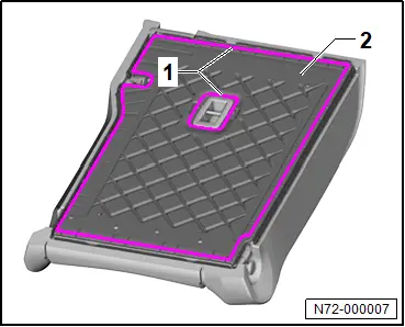
The back panel trim is bonded to the backrest frame over its entire surface.
– Apply heat from hot air blower -V.A.G 1416- to entire surface of back panel trim -1-, and carefully detach back panel trim from backrest frame -2-.

Installing
Install in reverse order of removal, observing the following:
– Apply adhesive -1- → Electronic parts catalogue (ETKA) onto outer surface of backrest frame -2-.
– Align back panel trim evenly relative to outer edges of backrest frame -2- and opening for child seat anchor cover in rear seat backrest.
– As soon as desired position has been found, press on back panel trim firmly.
Removing and installing trim for locking mechanism
Removing and installing trim for locking mechanism
Removing
– Remove head restraint → Rep. gr.72; Removing and installing head restraint.
– Using a screwdriver, detach upper and side piping strip for cover in area of locking mechanism trim from rear seat backrest.
Important
● The aid of an additional person is required for the subsequent work steps.
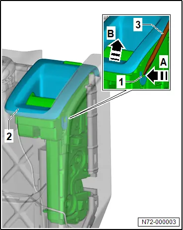
– Using commercially available plastic wedge, carefully push cover next to locking mechanism trim -2- outwards.
– Using screwdriver -3-, press locking device -1- in direction of -arrow A-, and hold it there.
– Repeat procedure on other side.
– Remove locking mechanism trim -2- in direction of -arrow B-.
Installing
Install in reverse order of removal, observing the following:
Important
● The rear seat backrest locking mechanism must work smoothly.
Removing and installing locking mechanism for rear seat backrest
Removing and installing locking mechanism for rear seat backrest
Removing
– Remove locking mechanism trim → Rep. gr.72; Removing and installing locking mechanism trim.
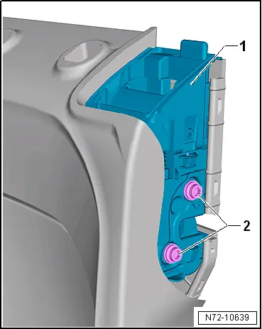
– Using commercially available plastic wedge, push cover (exclusively in area of locking mechanism for rear seat backrest) outwards.
– Unscrew bolts -2-.
– Remove locking mechanism for rear seat backrest -1-.
Installing
Install in reverse order of removal, observing the following:
Tightening torques
♦ → Rep. gr.72; Assembly overview – locking mechanism
Removing and installing trim frame for load-through hatch
Removing and installing trim frame for load-through hatch
Special tools and workshop equipment required
♦ hook -T40207-
♦ lever -T10039-
Removing
– Fold down centre armrest, and open flap for load-through hatch.
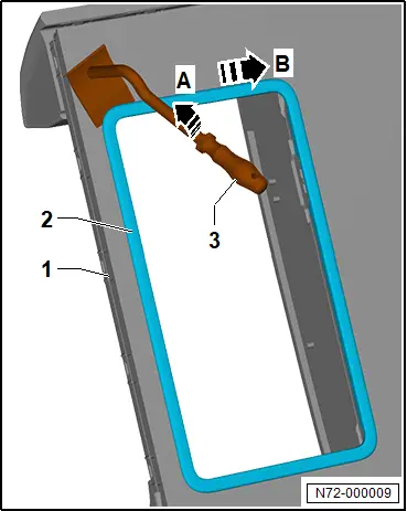
– Release locking devices -2- using hook -T40207- -3-.
– Using commercially available plastic wedge, unclip flap catch trim -1- in direction of -arrow- .

– Using lever -T10039- -3-, lever trim frame for load-through hatch -2- in direction of -arrow A- off rear seat backrest -1-.
– Start levering off in the upper left corner, and proceed in direction of -arrow B-.
– Remove trim frame for load-through hatch -2-.
– Push cover and padding of rear seat backrest slightly to one side, and unclip stop strip -1- in direction of -arrow-.
– Remove stop strip -1-.

Installing
Install in reverse order.
Removing and installing flap for load-through hatch
Removing and installing flap for load-through hatch
Removing
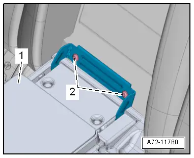
– Open flap for load-through hatch -1-.
– Unscrew bolts -2-.
– Remove flap for load-through hatch -1-.
Installing
Install in reverse order of removal, observing the following:
– Fit flap for load-through hatch -1-, and tighten bolts -2- hand-tight only.
– Close flap for load-through hatch, and align it.
– Carefully open flap for load-through hatch -1-, and tighten bolts -2- firmly.
Tightening torques
♦ → Rep. gr.72; Assembly overview – centre armrest
Removing and installing centre armrest
Removing and installing centre armrest
Removing
– Open flap for load-through hatch -2- by approx. 1/3.
– Unscrew bolts -3-.
– Remove centre armrest -1-.

Installing
Install in reverse order of removal, observing the following:
Tightening torques
♦ → Rep. gr.72; Assembly overview – centre armrest