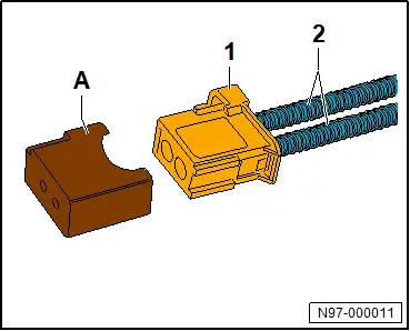
Wiring. Wires and lines
- Repair instructions for airbag and belt tensioner wiring
- Repair instructions for CAN bus wires
- Repair notes on FlexRay wires
- Repairing aerial wires
- Repairing 0.13 mm² - 6 mm² wire
- Repairing wires with a cross section of 10 mm² or 16 mm²
- Repairing 2.5 mm, 4 mm or 6 mm aluminium wires with a single crimp connector
- Section repairs to electrical wiring
- Repairs to safety-relevant wiring
- Repairing fibre optic cables
- Removing and installing fibre optic cable of wiring harness connector
Repair instructions for airbag and belt tensioner wiring
Repair instructions for airbag and belt tensioner wiring
♦ Repairs may be carried out on a maximum of 2 repair positions.
♦ Crimp connectors must be shrink-fitted.
♦ Do not introduce the repaired wiring back into the wiring harness.
♦ Mark the repair position clearly with yellow insulating tape.
♦ Carry out repairs at a maximum distance of 30 cm from the connector housing.
♦ Wires leading to airbags and igniters are twisted with a lay length of 20 ± 5 mm. The lay length must be considered during repair work.
♦ Both wires must have the same length for repairs. When wires -1- and -2- are twisted, the lay length of -a- = 20 mm ± 5 must be adhered to without fail.
♦ No section of the wire -arrow- may be longer than dimension -b- = 100 mm without a twist.
Repair instructions for CAN bus wires
Repair instructions for CAN bus wires
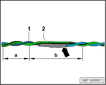
♦ Unshielded, twisted-pair lines -1- and -2- with a cross section of 0.13 mm² or 0.35 mm² are used for CAN bus wiring.
♦ Both CAN bus wires must have the same length.
♦ It is not permitted to repair the individual cores.
♦ Repairs to CAN bus wires must be carried out observing the correct cross section and, if possible, the corresponding colour coding; allocation → Electronic parts catalogue (ETKA).
♦ It is important to make sure that the length of the CAN wires after repairs does not deviate by more than ±50 mm from the original wire length.
♦ No section of the wire -arrows- may be longer than dimension -a- = 100 mm without a twist.
♦ Mark the area of repair with yellow insulation tape to make it easy to identify.
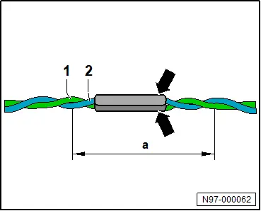
♦ Crimping of wires with connectors is to be carried out according to the same procedure.
♦ The repair areas -arrows- may be above one another.
♦ For colour codes of CAN bus wires, refer to the current flow diagram. → Current flow diagrams, Electrical fault finding and Fitting locations
♦ Cable tails with connectors must be crimped in accordance with the repair instructions given above.

Repair notes on FlexRay wires
Repair notes on FlexRay wires
A twisted two-core sheathed cable or an unsheathed, twisted two-core cable -1- and -2- with a cross section of 0.35 mm2 is used as a FlexRay wire.
♦ Repairs are only permissible for specific wires from → Electronic parts catalogue (ETKA).
♦ Both cores must be of same length.
♦ Mark the repair position, e.g. with yellow insulating tape.
♦ When repairing both cores, same specifications apply as for repairs to a single core.
Sheathed wires:
When twisting the wires -1- and -2-, the lay length dimension -a- = 30 mm must be considered.
No section of the wire may be longer than dimension -b- = 50 mm without a twist -arrow-.
Important

● The maximum wire length with the sheath removed corresponds to dimension -b- = 100 mm.
● Protect repair location with a heat-shrink hose. Wrap water-proof insulating tape around the stripped wire.
● In addition, both repair locations -arrows- must be arranged offset relative to one another by one lay length dimension -a- = 30 mm.
● Crimping of wires with connectors must be carried out according to the same procedure.
Wires without sheathing:
When twisting the wires -1- and -2-, the lay length dimension -a- = 20 mm must be considered.
No section of the wire may be longer than dimension -b- = 40 mm without a twist -arrow-.
Important
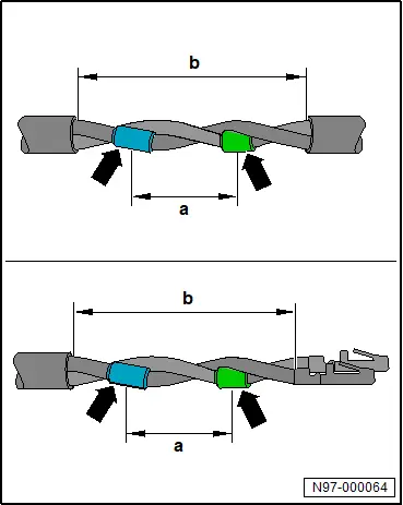
● In addition, both repair locations must be arranged offset relative to one another by one lay length dimension -a- = 20 mm.
● Crimping of wires with connectors must be carried out according to the same procedure.
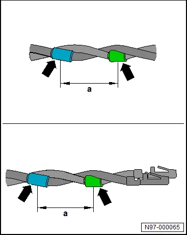
Repairing aerial wires
Repairing aerial wires
Special tools and workshop equipment required
♦ crimping tool RG 174 -VAS 6720/4-
♦ crimping tool RTK-031 -VAS 6720/2-
♦ repair kit, aerial wire -VAS 6720-
♦ wire stripping tool RG 174 -VAS 6720/3-
♦ wire stripping tool RTK-031 -VAS 6720/1-
Determining correct aerial wire system for repairs
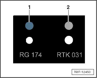
– Using gauge from repair set, aerial cable -VAS 6720-, check which aerial wire system needs to be repaired.
1 - System RG 174 = blue
2 - System RTK 031 = grey
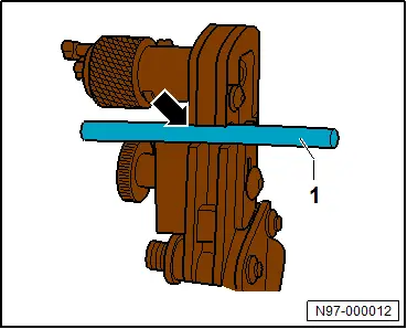
Cutting off the aerial wire
– Attach wire stripping tool RTK-031 -VAS 6720/1- or wire stripping tool RG 174 -VAS 6720/3-, as suitable, to crimping pliers from repair kit, aerial wire -VAS 6720-.
– Push aerial wire -1- into cutting mechanism -arrow-.
– Close crimping pliers, then open it again.
– Remove aerial wire -1-.
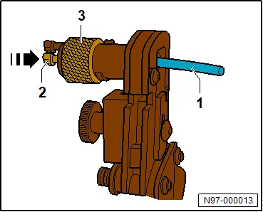
Stripping the shielding
– Push locating pin -2- in direction of -arrow- to stop into rotary cutter -3-.
– Push aerial wire -1- to stop into rotary cutter -3-.
Important
● Make sure that locating pin -2- is completely pushed out of rotary cutter -3-.
– Engage blade holder -1- in rotary cutter -3- in direction of -arrow A-.
Important
● Make sure that gap -arrow- is completely closed.
– Hold aerial wire -2- in position.
– Turn rotary cutter -3- in direction of -arrow B- until it is easy to turn.

– Pull out release pin -1- in direction of -arrow A- until blade holder is released from aerial wire -4-.
– Push locating pin -2- in direction of -arrow B- to stop into rotary cutter -3-.
Important
● Aerial wire -4- is pushed out of rotary cutter -3-.
– Remove aerial wire -4-.

– Remove shielding from aerial wire.
Stripping the outer sleeve
– Push aerial wire -1- as far as stop -2- into recess -arrow-.
– Close crimping pliers, then open it again.
– Pull out aerial wire -1-.
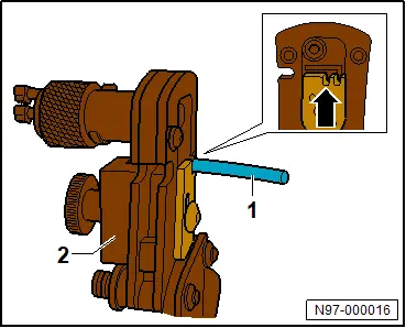
Stripping the inner insulation
– Push aerial wire -1- as far as stop -2- into recess -arrow-.
– Close crimping pliers, then open it again.
– Pull out aerial wire -1-.

Crimping the inner conductor
– Attach crimping tool RTK-031 -VAS 6720/2- or crimping tool RG 174 -VAS 6720/4-, as suitable, to crimping pliers from repair kit, aerial wire -VAS 6720-.
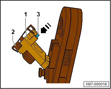
– Tilt back swinging positioner -1-.
– Open positioning piece -2-.
– Push inner contact -3- in direction of -arrow- to stop into swinging positioner -1-.
– Close positioning piece -2-.
Important
● Inner contact -3- is fixed in place.
– Tip swinging positioner -1- inwards.
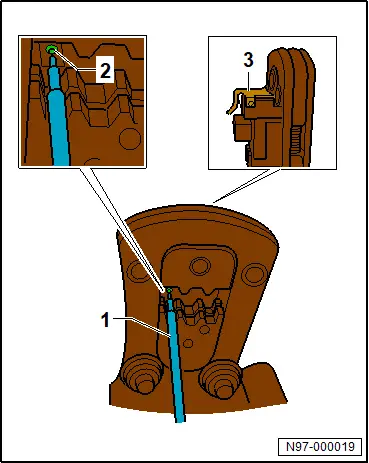
– Push aerial wire -1- into inner contact -2-.
– Close crimping pliers until crimping pliers open again automatically.
– Open positioning piece -3-.
– Remove aerial wire -1-.
Crimping the outer conductor
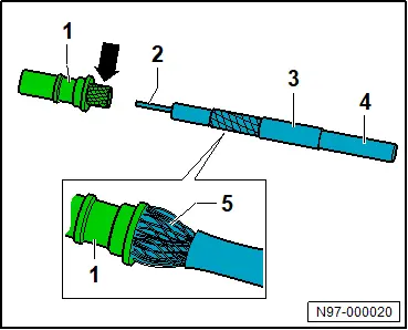
– Push sleeve -3- over aerial wire -4-.
– Push knurled contact part -arrow- of outer contact -1- over aluminium foil.
– Push shielding -5- into outer contact -1-.
– Push outer contact -1- entirely over inner conductor -2-.
– Push sleeve -3- over shielding -5-.
– Tilt back swinging positioner -1-.
– Insert outer contact -2- into centre profile -arrow- of crimping tool RTK-031 -VAS 6720/2- or crimping tool RG 174 -VAS 6720/4-, respectively.
– Close crimping pliers until crimping pliers open again automatically.
– Remove aerial wire -3-.
Repairing 0.13 mm² - 6 mm² wire
Repairing 0.13 mm² - 6 mm² wire
Special tools and workshop equipment required
♦ crimping pliers -VAS 1978/1-2-
♦ head adapter for crimping pliers 0.35 – 2.5 mm² -VAS 1978/1-1-
♦ head adapter for crimping pliers 4.0 – 6.0 mm² -VAS 1978/2A-
♦ hot air blower -VAS 1978/14A-
♦ interchangeable head for crimping pliers 0.13 – 0.5 mm² -VAS 1978/1-3-
♦ shrink element for hot air blower -VAS 1978/15A-
– Depending on the cross section of the respective wire, attach interchangeable head for crimping pliers 0.13 – 0.5 mm² -VAS 1978/1-3-, head adapter for crimping pliers 0.35 – 2.5 mm² -VAS 1978/1-1- or head adapter for crimping pliers 4.0 – 6.0 mm² -VAS 1978/2A- to crimping pliers -VAS 1978/1-2-.
– Cut out damaged section of wire.
Important
● If, after the damaged wire section has been cut out, both ends are too short for a repair using just one crimp connector, use a piece of yellow repair wire with 2 crimp connectors.
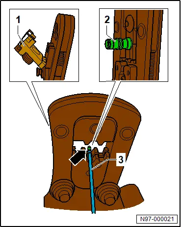
– Fit end of wire -2- as far as stop -arrow- in receiver on adapter head -1- with appropriate cross section.
– Press together crimping pliers, and hold it there.
– Pull out end of wire -2- from adapter head -1- to strip insulation.
– Open crimping pliers.
Important
● Insulation must be cut cleanly and removed from wire.
● Single wires must not be damaged.
– Strip end of other wire -2- in the same way.
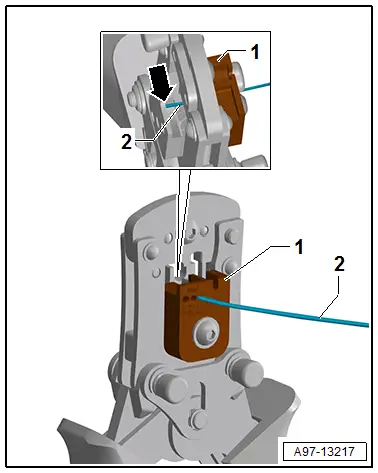
0.13-mm² wires:
– Push heat-shrink hose → Electronic parts catalogue (ETKA) onto electrical wire.
All vehicles (continued)
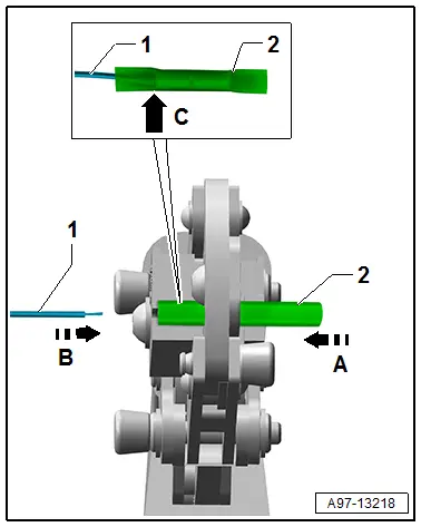
– Push crimp connector -2- in direction of -arrow A- as far as stop into crimp opening.
– Push stripped wire -1- in direction of -arrow B- into crimp connector -2-.
Important
● All single wires must be pushed into crimp connector -2-
● Insulation on wire -arrow C- must not be crimped.
– Press together crimping pliers, then open them.
– Remove wire -1- with crimp connector -2-.
– Crimp wire -1- with crimp connector -2- on other side as described.
– Pull out locking pin -1- to stop in direction of -arrow A-.
– Swivel upper part of adapter head -2- in direction of -arrow B-.
– Removed crimped crimp connector.

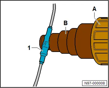
– Shrink the crimp connector -1- using hot air blower -VAS 1978/14A- -A- and shrink element for hot air blower -VAS 1978/15A- -B-.
0.13-mm² wires:
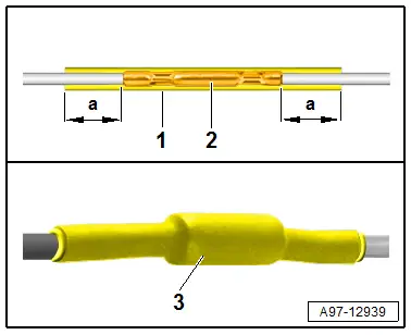
– Push heat-shrink hose -1- centrally over crimp connector -2-.
Important
● Dimension -a- must be even on both sides.
– Shrink heat-shrink hose -1- with hot air blower and shrink adapter from inside out.
– Inspect completed repair section -3-.
Important
● Heat-shrink hose -1- must be entirely shrunk.
● Adhesive must emerge from ends.
All vehicles (continued)
Premature release
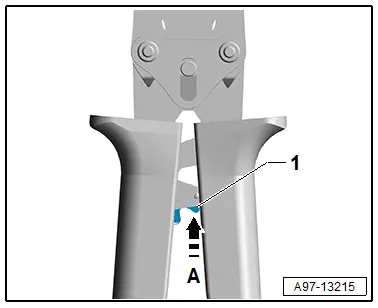
– Release release lever -1- in direction of -arrow A-.
– At same time, press together crimping pliers slightly and then open.
Repairing wires with a cross section of 10 mm² or 16 mm²
Repairing wires with a cross section of 10 mm² or 16 mm²
Special tools and workshop equipment required
♦ hot air blower -VAS 1978/14A-
♦ shrink adapter for hot air blower -VAS 1978/15A-
♦ wiring harness repair set -VAS 631 003-
Removing
– Attach crimping anvil and crimping die matching the wire cross-section to crimping pliers from wiring harness repair set -VAS 631 003-.
– Cut out damaged section of wire.
Important
● If, after the damaged wire section has been cut out, both ends are too short for a repair using just one crimp connector, use a piece of yellow repair wire with 2 crimp connectors.
– Strip required length of electrical wires according to cross-section.
♦ 10 mm² wires: 14 mm
♦ 16 mm² wires: 16.5 mm
Important
● Insulation must be cut cleanly and removed from wire.
● Single wires must not be damaged.
– Push heat-shrink hose onto one of the electrical wires → Electronic parts catalogue (ETKA).
– Position crimp connector -1- with first crimping point centrally on crimping anvil -2-.
Important
● Dimension -a- must be the same.
– Turn quick-action lever -3- in direction of -arrow- until crimp connector -1- is fixed.

– Insert stripped end of electrical wire -2- in direction of -arrow- to stop into crimp connector -1-.
Important
● All single wires must be pushed into crimp connector.
– Close and open crimping pliers several times until crimping anvil moves downwards automatically to start position.
Important
● Insulation on wire -2- must not be crimped.
– Proceed in the same way to crimp electrical wire with crimp connector -1- on the other side.
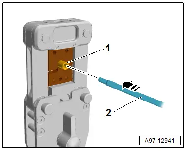
– Pull out locking pin -1- in direction of arrow -A- as far as it will go.
– Open adapter -2- in direction of arrow -B-.
– Remove crimped crimp connector.
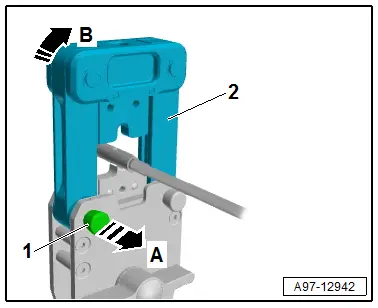
– Check crimped crimp connector.
♦ -A- – 10 mm², star-shaped crimp
♦ -B- – 16 mm², F-crimp

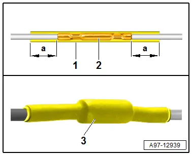
– Position heat-shrink hose -1- centrally over crimp connector -2-.
Important
● Dimension -a- must be even on both sides.
– Shrink heat-shrink hose -1- from inside outwards using hot air blower -VAS 1978/14A- and shrink adapter for hot air blower -VAS 1978/15A-.
– Inspect completed repair section -3-.
Important
● The heat-shrink hose must be entirely shrunk.
● Adhesive must emerge from ends.
Premature release
– Release release lever -1- in direction of -arrow A-.
– Turn quick-action lever -2- in direction of -arrow B- until crimping anvil is in the start position.
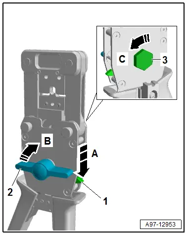
If premature release is not possible by hand:
– Release release lever -1- in direction of -arrow A-.
– Turn quick-action lever -3- in direction of -arrow C- until crimping anvil is in the start position.
Repairing 2.5 mm, 4 mm or 6 mm aluminium wires with a single crimp connector
Repairing 2.5 mm, 4 mm or 6 mm aluminium wires with a single crimp connector
Special tools and workshop equipment required
♦ hot air blower -VAS 1978/14A-
♦ shrink adapter for hot air blower -VAS 1978/15A-
♦ wiring harness repair set -VAS 631 001-
♦ wiring harness repair set -VAS 631 003-
Note
Copper wires are used for repairs → Electronic parts catalogue (ETKA).
Removing
– Attach crimping anvil, crimping die and contact positioner with contact locking device matching the wire cross-section to crimping pliers from wiring harness repair set -VAS 631 003-.
– Cut out damaged section of wire.
– Insert end of wire from front to stop into appropriate recess in wire stripper from wiring harness repair set -VAS 631 001-.
– Press together wire stripper, then open it again.
– Remove stripped wire.
Important
● Insulation must be cut cleanly and removed from wire.
● Single wires must not be damaged.
– Strip end of other electrical wire in the same way.

– Push heat-shrink hose → Electronic parts catalogue (ETKA) onto electrical wire.
– Insert crimp connector -1- into contact positioner -2-.
Important
● The crimp connector -1- must be flush -arrow A- with the contact positioner -2-.
– Push contact locking device -3- to stop in direction of -arrow B- until crimp connector -1- is fixed.
Important
● Lugs -4- on crimp connector -1- must engage in groove -5- on contact locking device -3-.

– Insert stripped end of wire -2- to stop in direction of -arrow- into crimp connector -1-.
Important
● All single wires must be pushed into crimp connector -1-
● End of insulation of wire -2- should reach no further than to front edge of insulation crimp.
– Close crimping pliers until crimping pliers open again automatically.
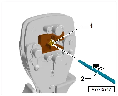
– Push contact locking device -2- to stop in direction of -arrow-.
– Remove crimp connector -1- from contact positioner -3-.
– Turn crimping pliers over.
– Crimp wire -1- with crimp connector -2- on other side as described.

– Pull out locking pin -1- in direction of arrow -A- as far as it will go.
– Open adapter -2- in direction of arrow -B-.
– Remove crimped crimp connector.

– Check crimped crimp connector.
Important
● Dimension -A- = 0.1 mm ... 1.0 mm
● The end of insulation -arrow- should reach no further than to the front edge of the insulation crimp.
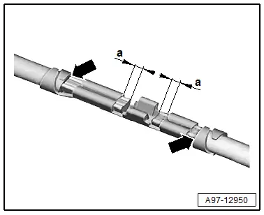
– Push heat-shrink hose -1- centrally over crimp connector -2-.
Important
● Dimension -a- must be even on both sides.
– Shrink heat-shrink hose -1- from inside outwards using hot air blower -VAS 1978/14A- and shrink adapter for hot air blower -VAS 1978/15A-.
– Inspect completed repair section -3-.
Important
● Heat-shrink hose -1- must be entirely shrunk.
● Adhesive must emerge from ends.
Section repairs to electrical wiring
Section repairs to electrical wiring
Removing
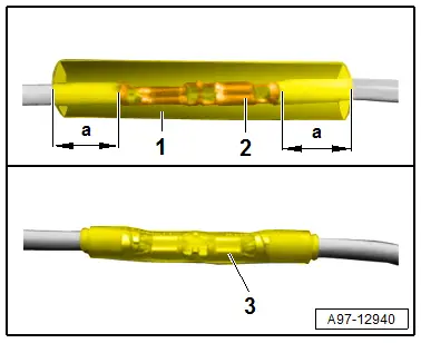
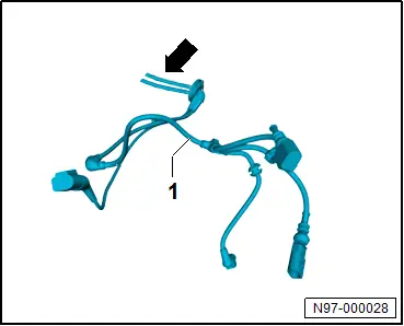
– Separate damaged wire at intended location -arrow- of old wire -1-.
– Connect new wire -1- at respective location -arrow-.
Repairs to safety-relevant wiring
Repairs to safety-relevant wiring
Special tools and workshop equipment required
♦ wiring harness repair set -VAS 1978-
Note
ISO 26262 is an ISO standard for safety-relevant electrical/electronic systems in motor vehicles. The implementation of the standard is intended to ensure the functional safety of a system with electrical/electronic components in motor vehicles.
Safety-relevant wiring suitable for repairs
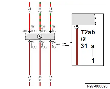
Safety-relevant wires that may be repaired are labelled “_s” -1- at the end of the potential name in the circuit diagram. Due to increased safety requirements, have a 2nd person inspect the repair in line with the “4-eyes principle”.
– Identify safety-relevant wires in → Current flow diagrams, Electrical fault finding and Fitting locations.
– Carry out repair using approved wiring harness repair set -VAS 1978-.
– Have repair inspected by a 2nd person.
Safety-relevant wiring not suitable for repairs
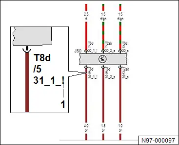
Safety-relevant wires that must not be repaired are labelled “_!” at the end of the potential name in the circuit diagram -1-. No repairs are permissible due to increased safety requirements.
– Identify safety-relevant wires in → Current flow diagrams, Electrical fault finding and Fitting locations.
– Renew wires completely, and route them according to their original installation position.
Important
● Route wires in such a way that there is no risk of them becoming trapped or abraded.
● Secure wires to wiring harness approx. every 20 cm.
Repairing fibre optic cables
Repairing fibre optic cables
Special tools and workshop equipment required
♦ cutting pliers -VAS 6228-
♦ pliers for corrugated tube installation -VAS 6223/10-
♦ repair kit for fibre optic cables -VAS 6223B-
Replace a damaged fibre optic cable with a new cable from repair kit for fibre optic cables -VAS 6223B-. Prepare new cable using the repair kit, and route it parallel to the damaged fibre optic cable.
Note
→ Vehicle diagnostic tester can be used to determine between which components the fibre optic cable is damaged.
Cutting fibre optic cable to size
– Attach tool head to pliers for fibre-optic cables from repair kit.
– Determine required length of fibre optic cable.
– Open pliers. Insert length of fibre optic cable to be cut -1- in direction of -arrow- into cutting hole.
– Close pliers to cut the fibre optic cable to size.

Stripping fibre optic cable
– Open pliers.
– Push stripping lever to stop in direction of -arrow-.
– Insert fibre optic cable into the stripping hole.
Important
● Fibre optic cable must be flush with the rear of the cutting pliers.
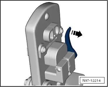
– Close pliers, and hold them there.
– Push stripping lever to stop in direction of -arrow-.
– Remove fibre optic cable.

Cutting precisely
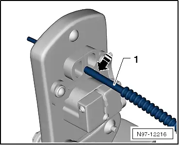
– Insert fibre optic cable -1- into the cutting hole.
Important
● Insulation must be lying against stop of cutting station.
– Remove pliers and fibre optic cable -1-.
Important
● There must not be any burrs on the end face.
Fitting brass pin contact to fibre optic cable
– Change tool head on pliers.
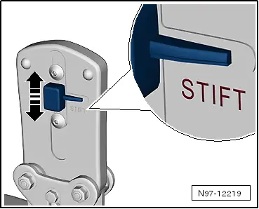
– Push locking element on tool head in direction of -arrow-.
Important
● Lettering “STIFT” must be visible.
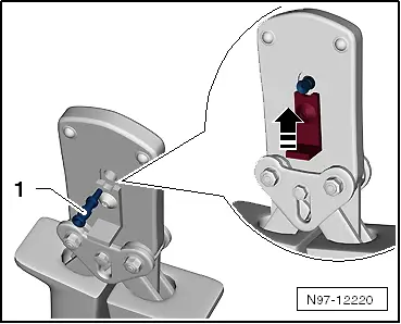
– Insert brass pin contact -1- into mounting.
– Press locking lever on tool head in direction of -arrow- to locked position.
– Insert fibre optic cable to spring-loaded stop into brass pin contact -arrow-.
– Close pliers completely, then open them again.
– Remove fibre optic cable with brass pin contact -arrow-.

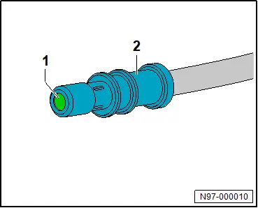
– Check that the brass pin contact -2- is correctly attached to fibre optic cable -1-.
Important
● 4 crimping points must be visible on the brass pin contact -2-.
● Make sure that the brass pin contact -2- cannot be pulled off the fibre optic cable -1- by hand.
– Check fibre optic cable for damage -1-.
Important
● The end face of the fibre optic cable -1- must be located 0.01 … 0.1 mm behind the brass pin contact -2-.
Fitting corrugated tube onto fibre optic cable
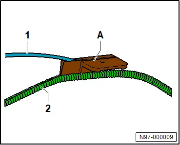
– Use cutting pliers -VAS 6228- to cut corrugated tube to required length.
Important
● Corrugated tube must be cut at wave crest.
● When the corrugated tube is installed, it must be heard to engage in the housing of the fibre optic cable.
– Insert fibre optic cable -1- into pliers for corrugated tube installation -VAS 6223/10- -A-.
– Apply pliers -A- at slot in corrugated tube -2-.
– Push pliers -A- along corrugated tube -2-.
– Insert fibre optic cable -1- into corrugated tube -2-.
Removing and installing fibre optic cable of wiring harness connector
Removing and installing fibre optic cable of wiring harness connector
Special tools and workshop equipment required
♦ protective cap for cable connectors -VAS 6223/9-
Removing
– Disconnect fibre optic cable connector from control unit.
– Mark lines to ensure proper allocation.
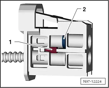
– Release fastener -1-.
– Release secondary fastener -2-.
– Remove fibre optic cable.
Installing
Install in reverse order of removal, observing the following:
– Install fibre optic cable in accordance with markings.
– Push corrugated tube -2- into connector -1-.
– Seal connector -1- using protective cap for cable connectors -VAS 6223/9- -A-.