V-5 Compressor - Description and Operation
GENERAL INFORMATION
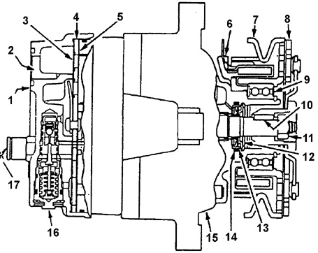
V-5 Compressor - Longitudinal Section
1. COMPRESSOR REAR COVER.
2. INLET PORT.
3. REAR COVER GASKET.
4. DISTRIBUTION PLATE.
5. VALVE PLATE WITH REED VALVES.
6. CLUTCH SOLENOID COIL.
7. PULLEY.
8. CLUTCH DRIVEN PLATE.
9. PULLEY BEARING.
10. HUB-TO-SHAFT KEY.
11. NUT.
12. SEAL RETAINING RING.
13. LIP SEAL.
14. O-RING.
15. CRANKCASE.
16. COMPRESSOR CONTROL VALVE.
17. PRESSURE RELIEF VALVE.
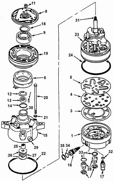
V-5 Compressor Construction
1. COMPRESSOR REAR COVER.
2. SUCTION PORT (NOT SHOWN).
3. REAR COVER GASKET.
4. DISTRIBUTION PLATE.
5. VALVE PLATE WITH REED VALVES.
6. CLUTCH SOLENOID COIL.
7. PULLEY (NOT SHOWN).
8. CLUTCH DRIVEN PLATE.
9. PULLEY BEARING.
10. HUB-TO-SHAFT KEY.
11. NUT.
12. SEAL RETAINING RING.
13. LIP SEAL.
14. O-RING.
15. CRANKCASE.
16. COMPRESSOR CONTROL VALVE.
17. PRESSURE RELIEF VALVE.
18. BEARING RETAINING RING.
19. PULLEY WITH CLUTCH DRIVE PLATE.
20. THROUGH BOLT.
21. GASKET.
22. O-RING BETWEEN CRANKCASE AND CYLINDER BLOCK.
23. CYLINDER BLOCK WITH SHAFT AND SWASH PLATE ASSEMBLY.
24. O-RING BETWEEN REAR COVER AND CYLINDER BLOCK.
25. SPACER BUSHING.
26. THRUST BEARING RING.
27. THRUST BEARING.
28. FAN AND LOW PRESSURE SWITCHES.
29. DRAIN PLUG.
30. KEYWAY.
31. SHAFT.
32. PRESSURE RELIEF VALVE O-RING.
33. O-RINGS FOR FAN AND LOW PRESSURE SWITCHES.
34. CONTROL VALVE O-RING.
35. RETAINING RING
The V-5 variable displacement compressor is designed for automotive air conditioning systems and provides the required capacity under all operating conditions.
It operates under all loads without periodic cycling on and off.
The basis of the compressor is a reciprocating swash plate type unit with five axially arranged cylinders.
The displacement regulator consists of a valve with a bellows-type sensing device located in the rear cover of the compressor.
The valve responds to pressure in the compressor suction chamber.
The swash plate angle and compressor displacement depend on the pressure difference
between the compressor crankcase and the suction chamber.
When high compressor capacity is required, suction pressure exceeds the set value and the valve is in the open position.
In this case the crankcase is connected to the suction chamber and the pressures are equal. The swash plate is set to maximum capacity.
When required capacity decreases and suction pressure reaches the set value, the valve opens access for discharge gas into the crankcase and disconnects it from the suction chamber.
The equilibrium swash plate angle is established by forces acting on the pistons.
A slight increase in pressure difference between the crankcase and suction chamber produces a resultant piston force that turns the plate toward reduced compressor capacity.
The compressor has an original lubrication system. Drainage of the internal crankcase cavity is carried to the suction cavity through the rotating swash plate to lubricate its bearings. The rotating swash plate also acts as an oil separator, separating oil from gas and maintaining the normal working oil level in the crankcase.
The crankcase can hold up to 120 ml of refrigerant oil.
Therefore, after removing the compressor from the vehicle, drain all oil through the drain plug and measure the volume of oil that was in the unit.
After this, the oil may be discarded.
drain all the oil through the drain plug and measure the amount of oil that was in the unit. After that the oil can be drained.
Each compressor supplied as a service part is filled with 240 ml of refrigerant oil.
This oil must be drained and its volume measured.
The new compressor must be filled with fresh oil in an amount equal to
the volume of oil drained from the old compressor. (The volume of drained oil must be recorded.)
Test yourself
A quick Daewoo Nexia quiz: every answer comes with an explanation and a link to the manual page.