Air Conditioning System Control
GENERAL INFORMATION
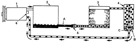
Typical A/C system diagram: A. LIQUID LINE
B. DESICCANT CARTRIDGE
C. OPENING FOR MIXING REFRIGERANT VAPOR WITH REFRIGERANT OIL
1. COMPRESSOR
2. CONDENSER
3. EVAPORATOR
4. RECEIVER-DRIER
5. ORIFICE TUBE
6. PRESSURE RELIEF VALVE
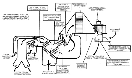
Typical air flow diagram of the A/C system

Cross-section of the A/C unit: A. BLOWER MOTOR
B. INLET AIR DOOR
C. AIR DISTRIBUTION DOOR
D. AIR DISTRIBUTION DOOR
E. WINDSHIELD DEFROST DOOR
F. HEATER CORE
G. EVAPORATOR CORE

A/C control panel. ELECTRICAL CONTROL
1. AIR RECIRCULATION MODE SWITCH BUTTON
2. A/C SYSTEM SWITCH BUTTON
3. BLOWER OFF
4. BLOWER SPEED CONTROL KNOB
VACUUM ACTUATOR
5. VENT MODE - AIR FLOWS THROUGH THE FRONT PANEL OUTLETS
6. COMBINED VENT AND HEAT MODE - AIR FLOWS THROUGH THE FRONT AND LOWER OUTLETS
7. HEAT MODE - AIR FLOWS THROUGH THE LOWER OUTLETS
8. DEFROST (DEFOG) MODE - AIR FLOWS TO THE WINDSHIELD
A. MINIMUM TEMPERATURE.
B. MAXIMUM TEMPERATURE
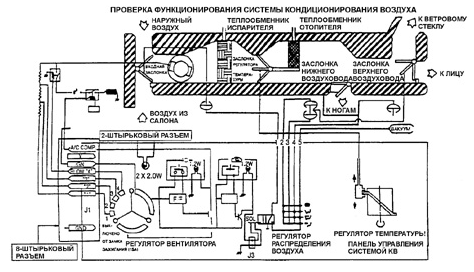
A/C Control System Diagram
Controls.
The A/C system is controlled by the controls located on the panel. The compressor clutch solenoid and the blower motor are connected by wires to the control panel. In the OFF position of the control,
the blower motor electrical circuit is open. Airflow is provided when the control is set to one of four operating positions. Cooled and dehumidified air enters the vehicle interior when MAX,
NORMAL, BI-LEVEL or DEFROST mode is selected. The air temperature is set using the rotary control located on the control panel. The control lever is connected by a control cable to a movable damper, the position of which
determines the airflow through the heater core. When the control is moved from one extreme position to the other, the cable drive must provide full range of damper movement. The position of the temperature control damper does not
, NORMAL, BI-LEVEL modes or the windshield defrost (DEFROST) mode. Air temperature is set using the rotary control located on the control panel. The control knob is connected by a control cable to the movable door, the position of which
determines the airflow through the heater core. When the control is moved
The cable drive must allow the damper to move through its full range of travel from one extreme position to the other. The position of the temperature control damper does not
depend on the mode selector switch. The damper control cable runs from the right side of the A/C unit. On some vehicle models, the damper is equipped with an electric actuator and there is no cable. On some
vehicles, the electric engine cooling fan is not part of the A/C system. However, the fan automatically operates when the A/C system is set to MAX, NORMAL or BI-LEVEL mode. On some vehicles the fan also operates when DEFROST mode is selected. This
On some vehicles the electric engine cooling fan is not part of the A/C system. However, the fan switches on automatically when the A/C system is turned on to MAX, NORMAL or
controlled by the electronic control unit (ECU) through the fan relay.
The A/C control system design helps prevent overheating of the compressor head. In this case the A/C system operates more efficiently. On certain vehicle models the electric engine fan switches off automatically when the vehicle reaches a speed of 56 km/h, when the cooling intensity
Vacuum Lines
The vacuum lines are connected through a connector block to the switch on the A/C control panel. If the seal is broken or an individual line is damaged, it is not necessary to replace the entire set of lines. It is sufficient to
cut out the faulty section of line and insert a plastic connecting tube in its place. If the entire line must be replaced, cut all lines from the connector block and then connect them directly to the vacuum switch.
Vacuum Reservoir
control system. If the seal is broken or an individual line is damaged, it is not necessary to replace the entire set of lines. It is sufficient to
cut out the faulty section of line and install a plastic
connecting tube in its place. If it is necessary to replace the entire line, cut
all lines from the connector block and then connect them directly to the vacuum switch.
Vacuum receiver.
During hard acceleration, the vacuum in the engine intake manifold decreases. In this case, the check valve isolates the vacuum reservoir from the engine, allowing the vacuum actuator to continue operating the A/C control system.
Relays and Switches
Daewoo Nexia: Relays and Switches
High-Pressure Switch
Test yourself
A quick Daewoo Nexia quiz: every answer comes with an explanation and a link to the manual page.